work must be performed inside the air duct. Sampling of air in ducts wider than 8 feet is accomplished by using the ST-10 inlet sampling tube. If the tube is shorter than the width of the air duct, install the end plug into the inlet tube as shown in Figure 4 and sup- port the end opposite the duct smoke detector.
Install the inlet tube as follows:
1.Drill a 3/4-inch hole in the duct directly opposite the hole
already drilled for the inlet tube. Make sure the hole is 1 to 2″ below the inlet hole on the opposite side of the
duct to allow for moisture drainage.
2.Slide the inlet tube with the flange into the housing bushing that meets the air flow first. Position the tube so that the arrows point into the air flow. Secure the tube flange to the housing bushing with two #6 self-tapping screws.
3.From inside the duct, couple the other sections of the in- let tube to the section already installed using the 1/2-inch conduit fittings supplied. Make sure that the holes on both of the air inlet tubes are lined up and facing into the air flow.
4.Trim the end of the tube protruding through the duct so that 1 to 2″ of the tube extend outside the duct. Plug this
end with the end plug and tape closed any holes in the protruding section of the tube. Be sure to seal the duct when the tube protrudes.
NOTE: An alternate method to using the ST-10 is to use two ST-5 inlet tubes. Remove the flange from one of the tubes and install as described above. After the installation, use electrical tape to close off some of the sampling holes so that there are a total of 10 to 12 holes spaced as evenly as possible across the width of the duct.
NOTE: Air currents inside the duct may cause excessive vibration, especially when the longer sampling tubes are used. In these cases a 3 inch floor flange (available at most plumbing supply stores) may be used to fasten the sampling tube to the other side of the duct. When using the flange/connector mounting technique, drill a 1-inch to 11/4-inch hole where the flange will be used.
[5.4.3] Modifications of Inlet Sampling Tubes
There may be applications where duct widths are not what is specified for the installation. In such cases, it is permis- sible to modify an inlet sampling tube that is longer than necessary to span the duct width.
Use a 0.193-inch diameter (#11) drill and add the appropriate number of holes so that the total number of holes exposed to the air flow in the duct is 10 to 12. Space the additional holes
as evenly as possible over the length of the tube.
NOTE: This procedure should only be used as a temporary fix. It is not intended as a permanent substitute for ordering the correct length tubes.
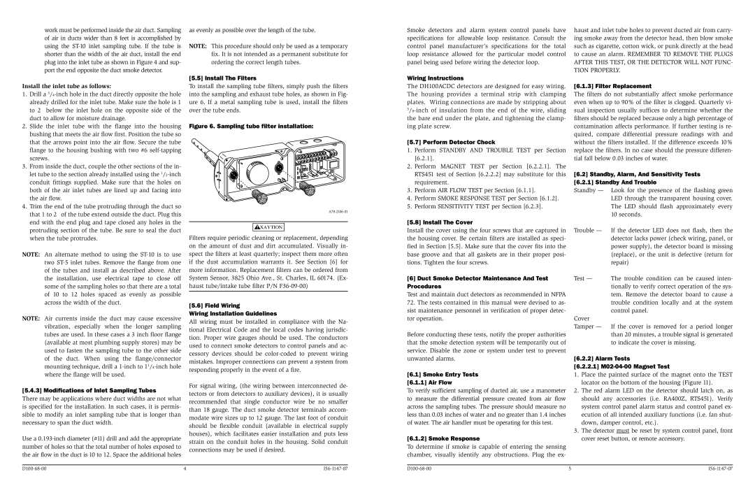
[5.5] Install The Filters
To install the sampling tube filters, simply push the filters into the sampling and exhaust tube holes, as shown in Fig- ure 6. If a metal sampling tube is used, install the filters over the tube ends.
Figure 6. Sampling tube filter installation:
A78-2106-01

 CAUTION
Filters require periodic cleaning or replacement, depending on the amount of dust and dirt accumulated. Visually in- spect the filters at least quarterly; inspect them more often if the dust accumulation warrants it. See Section [6] for more information. Replacement filters can be ordered from System Sensor, 3825 Ohio Ave., St. Charles, IL 60174. (Ex- haust tube/intake tube filter P/N F36-09-00)
[5.6] Field Wiring
Wiring Installation Guidelines
All wiring must be installed in compliance with the Na- tional Electrical Code and the local codes having jurisdic- tion. Proper wire gauges should be used. The conductors used to connect smoke detectors to control panels and ac- cessory devices should be color-coded to prevent wiring mistakes. Improper connections can prevent a system from responding properly in the event of a fire.
For signal wiring, (the wiring between interconnected de- tectors or from detectors to auxiliary devices), it is usually recommended that single conductor wire be no smaller than 18 gauge. The duct smoke detector terminals accom- modate wire sizes up to 12 gauge. The last foot of conduit should be flexible conduit (available in electrical supply houses), which facilitates easier installation and puts less strain on the conduit holes in the housing. Solid conduit connections may be used if desired.
Smoke detectors and alarm system control panels have specifications for allowable loop resistance. Consult the control panel manufacturer’s specifications for the total loop resistance allowed for the particular model control panel being used before wiring the detector loop.
Wiring Instructions
The DH100ACDC detectors are designed for easy wiring. The housing provides a terminal strip with clamping plates. Wiring connections are made by stripping about 3/8-inch of insulation from the end of the wire, sliding the bare end under the plate, and tightening the clamp- ing plate screw.
[5.7] Perform Detector Check
1.Perform STANDBY AND TROUBLE TEST per Section [6.2.1].
2.Perform MAGNET TEST per Section [6.2.2.1]. The RTS451 test of Section [6.2.2.2] may substitute for this requirement.
3.Perform AIR FLOW TEST per Section [6.1.1].
4.Perform SMOKE RESPONSE TEST per Section [6.1.2].
5.Perform SENSITIVITY TEST per Section [6.2.3].
[5.8] Install The Cover
Install the cover using the four screws that are captured in the housing cover. Be certain filters are installed as speci- fied in Section [5.5]. Make sure that the cover fits into the base groove and that all gaskets are in their proper posi- tions. Tighten the four screws.
[6]Duct Smoke Detector Maintenance And Test Procedures
Test and maintain duct detectors as recommended in NFPA 72. The tests contained in this manual were devised to as- sist maintenance personnel in verification of proper detec- tor operation.
Before conducting these tests, notify the proper authorities that the smoke detection system will be temporarily out of service. Disable the zone or system under test to prevent unwanted alarms.
[6.1] Smoke Entry Tests
[6.1.1] Air Flow
To verify sufficient sampling of ducted air, use a manometer to measure the differential pressure created from air flow across the sampling tubes. The pressure should measure no less than 0.03 inches of water and no greater than 1.4 inches of water. The air handler must be operating for this test.
[6.1.2] Smoke Response
To determine if smoke is capable of entering the sensing chamber, visually identify any obstructions. Plug the ex-
haust and inlet tube holes to prevent ducted air from carry- ing smoke away from the detector head, then blow smoke such as cigarette, cotton wick, or punk directly at the head to cause an alarm. REMEMBER TO REMOVE THE PLUGS AFTER THIS TEST, OR THE DETECTOR WILL NOT FUNC- TION PROPERLY.
[6.1.3] Filter Replacement
The filters do not substantially affect smoke performance even when up to 90% of the filter is clogged. Quarterly vi- sual inspection usually suffices to determine whether the filters should be replaced because only a high percentage of contamination affects performance. If further testing is re- quired, compare differential pressure readings with and without the filters installed. If the difference exceeds 10% replace the filters. In no case should the pressure differen- tial fall below 0.03 inches of water.
[6.2] Standby, Alarm, And Sensitivity Tests [6.2.1] Standby And Trouble
Standby — Look for the presence of the flashing green LED through the transparent housing cover. The LED should flash approximately every 10 seconds.
Trouble — If the detector LED does not flash, then the detector lacks power (check wiring, panel, or power supply), the detector board is missing (replace), or the unit is defective (return for repair)
Test — The trouble condition can be caused inten- tionally to verify correct operation of the sys- tem. Remove the detector board to cause a trouble condition locally and at the system control panel.
Cover
Tamper — If the cover is removed for a period longer than 20 minutes, a trouble signal is generated to indicate the cover is missing.
[6.2.2] Alarm Tests
[6.2.2.1] M02-04-00 Magnet Test
1.Place the painted surface of the magnet onto the TEST locator on the bottom of the housing (Figure 11).
2.The red alarm LED on the detector should latch on, as should any accessories (i.e. RA400Z, RTS451). Verify system control panel alarm status and control panel ex- ecution of all intended auxiliary functions (i.e. fan shut- down, damper control, etc.).
3.The detector must be reset by system control panel, front cover reset button, or remote accessory.