[6.2.2] Alarm Tests

[6.2.2.1] M02-04-00 Magnet Test

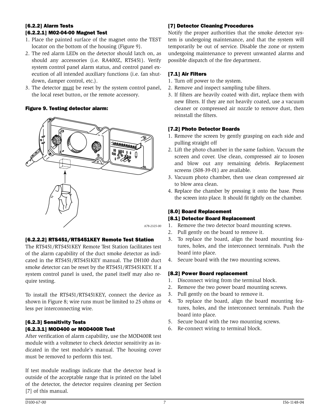
1.Place the painted surface of the magnet onto the TEST locator on the bottom of the housing (Figure 9).

2.The red alarm LEDs on the detector should latch on, as should any accessories (i.e. RA400Z, RTS451). Verify system control panel alarm status, and control panel ex- ecution of all intended auxiliary functions (i.e. fan shut- down, damper control, etc.).

3.The detector must be reset by the system control panel, the local reset button, or the remote accessory.

Figure 9. Testing detector alarm:

A78-2325-00

[6.2.2.2] RTS451/RTS451KEY Remote Test Station

The RTS451/RTS451KEY Remote Test Station facilitates test of the alarm capability of the duct smoke detector as indi- cated in the RTS451/RTS451KEY manual. The DH100 duct smoke detector can be reset by the RTS451/RTS451KEY. If a system control panel is used, the panel itself may also re- quire testing.

To install the RTS451/RTS451KEY, connect the device as shown in Figure 8; wire runs must be limited to 25 ohms or less per interconnecting wire.

[6.2.3] Sensitivity Tests

[6.2.3.1] MOD400 or MOD400R Test

After verification of alarm capability, use the MOD400R test module with a voltmeter to check detector sensitivity as in- dicated in the test module’s manual. The housing cover must be removed to perform this test.

If test module readings indicate that the detector head is outside of the acceptable range that is printed on the label of the detector, the detector requires cleaning per Section [7] of this manual.

[7] Detector Cleaning Procedures

Notify the proper authorities that the smoke detector sys- tem is undergoing maintenance, and that the system will temporarily be out of service. Disable the zone or system undergoing maintenance to prevent unwanted alarms and possible dispatch of the fire department.

[7.1] Air Filters

1.Turn off power to the system.

2.Remove and inspect sampling tube filters.

3.If filters are heavily coated with dirt, replace them with new filters. If they are not heavily coated, use a vacuum cleaner or compressed air nozzle to remove dust, then reinstall the filters.

[7.2] Photo Detector Boards

1.Remove the screen by gently grasping on each side and pulling straight off

2.Lift the photo chamber in the same fashion. Vacuum the screen and cover. Use clean, compressed air to loosen and blow out any remaining debris. Replacement screens (S08-39-01) are available.

3.Vacuum photo chamber, then use clean compressed air to blow area clean.

4.Replace the chamber by pressing it onto the base. Press the screen into place. It should fit tightly on the chamber.

[8.0] Board Replacement

[8.1] Detector Board Replacement

1.Remove the two detector board mounting screws.

2.Pull gently on the board to remove it.

3.To replace the board, align the board mounting fea- tures, holes, and the interconnect terminals. Push the board into place.

4.Secure board with the two mounting screws.

[8.2] Power Board replacement

1.Disconnect wiring from the terminal block.

2.Remove the two power board mounting screws.

3.Pull gently on the board to remove it.

4.To replace the board, align the board mounting fea- tures, holes, and the interconnect terminals. Push the board into place.

5.Secure board with the two mounting screws.

6.Re-connect wiring to terminal block.

D100-67-00

7

I56-1148-04

Page 7
Image 7
System Sensor D100-67-00 Alarm Tests 2.1 M02-04-00 Magnet Test, 2.2 RTS451/RTS451KEY Remote Test Station, Air Filters

D100-67-00, I56-1148-04 specifications

The System Sensor D100-67-00 and I56-1148-04 are advanced devices designed for fire detection and alarm systems, offering a range of features and technologies that cater to the needs of modern safety requirements.

The D100-67-00 is a high-performance photoelectric smoke detector that incorporates innovative sensing technology. It boasts a sophisticated optical chamber that enhances its ability to detect smoke particles effectively. This detector minimizes false alarms commonly caused by non-threatening, everyday activities such as cooking, making it ideal for residential and commercial applications. Its low profile design and sleek aesthetic also allow it to seamlessly blend into various environments. The D100-67-00's sensitivity is adjustable, ensuring that it can be calibrated according to specific needs or building codes, thereby enhancing its versatility.

Moreover, the D100-67-00 features a built-in sounder and visual indicators that provide immediate alerts. The device is equipped with a robust communication protocol that allows it to integrate with other fire alarm control panels and monitoring systems. This capability enhances the overall safety network by ensuring real-time communication of any fire incidents, a crucial feature in high-risk areas.

On the other hand, the System Sensor I56-1148-04 is an advanced heat detector that employs thermal sensing technology. It is designed to respond to rapid temperature increases, ensuring quick detection of potential fire hazards. This device is particularly beneficial in environments where smoke detectors might be prone to false alarms due to dust or steam, like kitchens or garages. The I56-1148-04 features a dual-heat sensing mechanism, allowing it to differentiate between normal temperature fluctuations and dangerous heat spikes, providing an extra layer of protection.

Both devices are engineered with durability in mind, adhering to strict industry standards. They are intended for long-term use, requiring minimal maintenance while still delivering reliable performance. Critical for emergency response, both detectors offer optional connectivity with control panels and monitoring solutions, allowing for comprehensive system integration.

In summary, the System Sensor D100-67-00 and I56-1148-04 are integral components of fire safety systems, with their advanced features and technologies ensuring efficient detection and alerting in diverse settings. These devices exemplify reliability and innovation, essential in safeguarding lives and property against fire hazards.