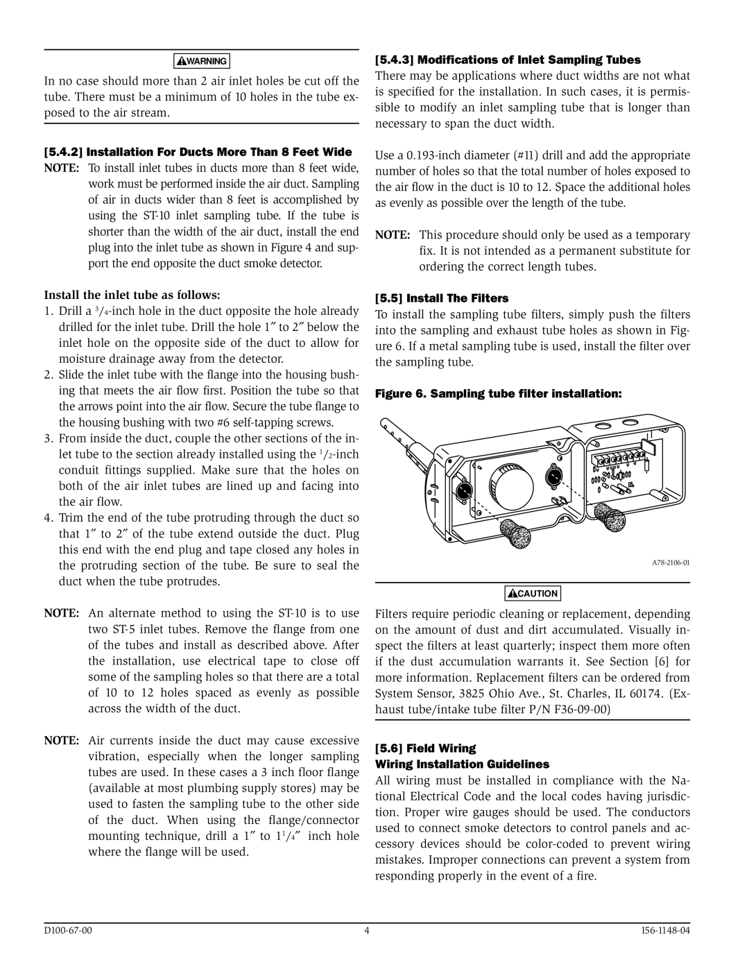
D100-67-00, I56-1148-04 specifications
The System Sensor D100-67-00 and I56-1148-04 are advanced devices designed for fire detection and alarm systems, offering a range of features and technologies that cater to the needs of modern safety requirements.The D100-67-00 is a high-performance photoelectric smoke detector that incorporates innovative sensing technology. It boasts a sophisticated optical chamber that enhances its ability to detect smoke particles effectively. This detector minimizes false alarms commonly caused by non-threatening, everyday activities such as cooking, making it ideal for residential and commercial applications. Its low profile design and sleek aesthetic also allow it to seamlessly blend into various environments. The D100-67-00's sensitivity is adjustable, ensuring that it can be calibrated according to specific needs or building codes, thereby enhancing its versatility.
Moreover, the D100-67-00 features a built-in sounder and visual indicators that provide immediate alerts. The device is equipped with a robust communication protocol that allows it to integrate with other fire alarm control panels and monitoring systems. This capability enhances the overall safety network by ensuring real-time communication of any fire incidents, a crucial feature in high-risk areas.
On the other hand, the System Sensor I56-1148-04 is an advanced heat detector that employs thermal sensing technology. It is designed to respond to rapid temperature increases, ensuring quick detection of potential fire hazards. This device is particularly beneficial in environments where smoke detectors might be prone to false alarms due to dust or steam, like kitchens or garages. The I56-1148-04 features a dual-heat sensing mechanism, allowing it to differentiate between normal temperature fluctuations and dangerous heat spikes, providing an extra layer of protection.
Both devices are engineered with durability in mind, adhering to strict industry standards. They are intended for long-term use, requiring minimal maintenance while still delivering reliable performance. Critical for emergency response, both detectors offer optional connectivity with control panels and monitoring solutions, allowing for comprehensive system integration.
In summary, the System Sensor D100-67-00 and I56-1148-04 are integral components of fire safety systems, with their advanced features and technologies ensuring efficient detection and alerting in diverse settings. These devices exemplify reliability and innovation, essential in safeguarding lives and property against fire hazards.

