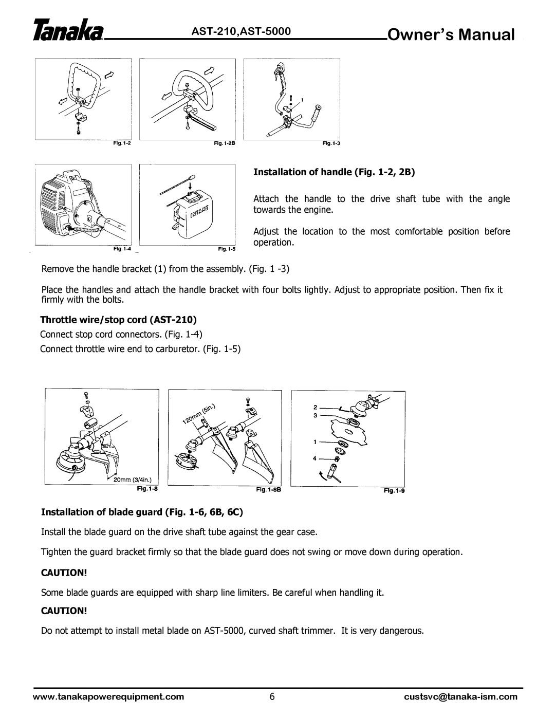
AST-210, AST-5000 specifications
The Tanaka AST-210 and AST-5000 are exceptional models in the lineup of outdoor power equipment, each designed to meet the varying needs of gardening professionals and enthusiasts alike. These machines are renowned for their reliability, performance, and advanced technological features.The Tanaka AST-210 is a lightweight, efficient grass trimmer, making it ideal for residential use and smaller commercial tasks. Weighing only 10 pounds, it offers great portability without sacrificing power. A key feature of the AST-210 is its powerful 21cc two-stroke engine, which provides impressive cutting performance, allowing users to tackle thick grass and weeds effortlessly. The model is equipped with a dual-line cutting head that ensures a clean and precise finish.
One notable aspect of the AST-210 is its ergonomic design, which includes a comfortable, vibration-reducing handle. This feature allows for extended use without causing fatigue. Additionally, the trimmer has a quick-release coupling that enables easy attachment and detachment of various accessories, making it versatile for different gardening tasks. The Advanced Start Technology incorporated in the AST-210 makes it easier to start the engine with minimal effort.
On the other hand, the Tanaka AST-5000 takes performance and durability to the next level. This professional-grade grass trimmer boasts a 50.8cc two-stroke engine, delivering exceptional power suitable for extensive areas and rugged conditions. With a unique anti-vibration system, the AST-5000 enhances user comfort, allowing for prolonged periods of operation.
One of the standout features of the AST-5000 is its high-capacity fuel tank, which reduces the need for frequent refueling during larger projects. Its heavy-duty cutting head is designed for commercial use, capable of accommodating a variety of line sizes to tackle different types of vegetation. The trimmer also features a solid steel drive shaft for enhanced durability and performance under tough conditions.
Both the AST-210 and AST-5000 incorporate Tanaka's commitment to environmental responsibility, with low emission engines that comply with stringent regulatory standards. Each model is designed with user-friendly controls, ensuring that even novice users can operate them effectively.
In conclusion, the Tanaka AST-210 and AST-5000 represent a robust choice for those seeking reliable and efficient grass trimming solutions. With their advanced technologies, ergonomic designs, and powerful engines, they stand out in the competitive field of outdoor power equipment, catering to both home gardeners and professional landscapers.

