TANDBERG D5018501 instruction sheet Supplied Components, RS232 Blanking Plate Installation

Models: D5018501

1 3
Download 3 pages 27.28 Kb
Page 1
Image 1
Installation of X-Port 10 with Director

Installation of X-Port 10 with Director

This document explains how to connect the X-Port 10 to the Director system. This feature allows easy connections for an external portable computer and automatic switching between the internal and external computer with the Director system.

Supplied Components:

1 Connector Box

1 RS232 Blanking Plate

1 Pair of export 10 Mounting Bracket (Left and Right)

2 T201-0036 Cables, 1 T201-0072 Cable, 1 T237-0072 Cable, 2 T112-0036 Cables, 1 T323- 0036 Cable, 1 T325-0072 Cable, 1 T324-0036 Cable, 1 T308-0036 Cable, 1 HD15D-Sub to BNC cable

1 TANDBERG Director label

4 #10-32 G-style panel nut retainer and 4 #10-32 x ¾” Black rack screw with washer

10 Black adhesive cable tie mounting base14 cable ties 4” long

2 #4-40 x 3/16” screws

1 instruction sheet

RS232 Blanking Plate Installation:

Install the blanking plate over the Computer 2 Serial connector located on the rear of the Smart 3000i projector unit using the 2 supplied #4-40 x 1/8” screws.

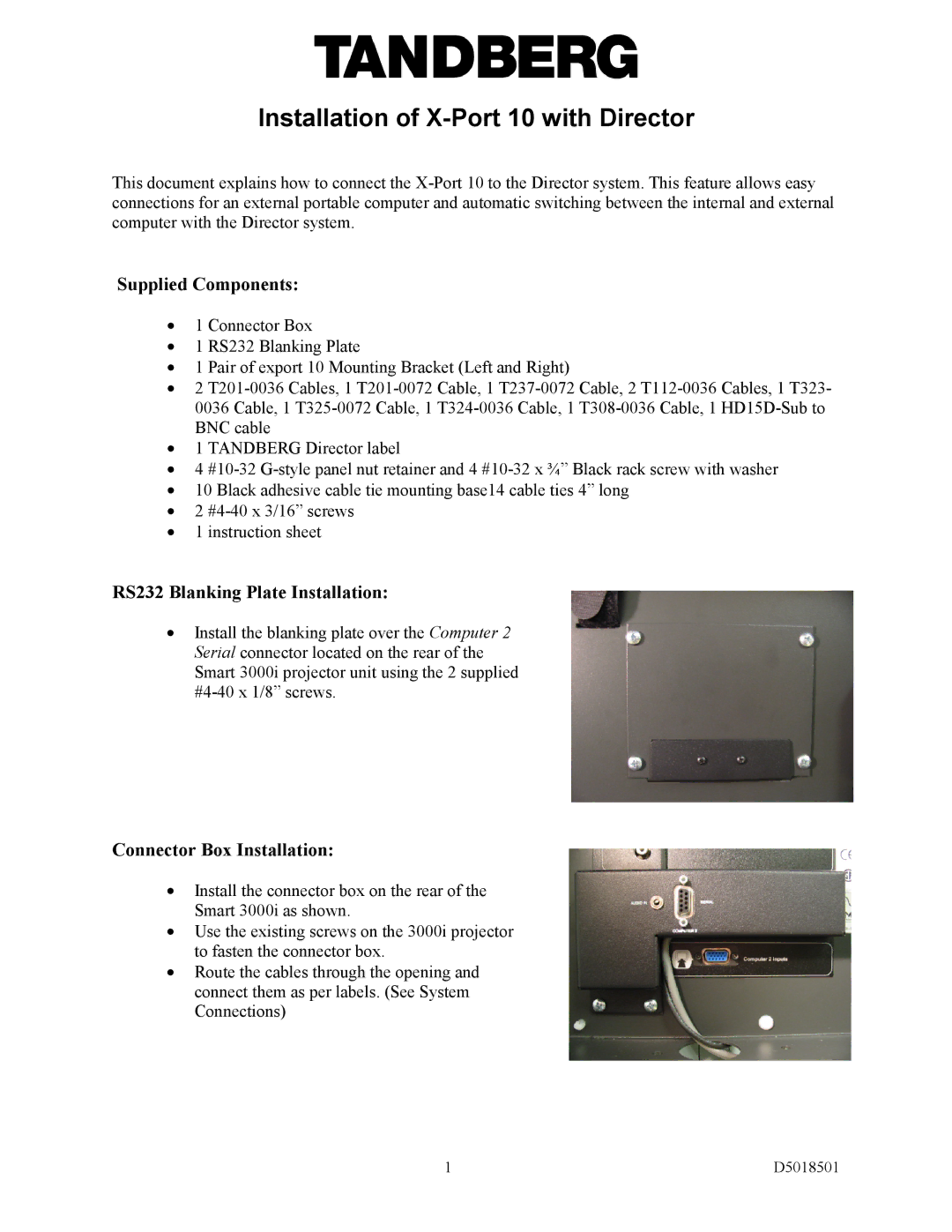
Connector Box Installation:

Install the connector box on the rear of the Smart 3000i as shown.

Use the existing screws on the 3000i projector to fasten the connector box.

Route the cables through the opening and connect them as per labels. (See System Connections)

1

D5018501

Page 1
Image 1
TANDBERG D5018501 instruction sheet Supplied Components, RS232 Blanking Plate Installation, Connector Box Installation