TANDBERG D5018501 X-Port 10 Installation, DC Power Connection to X-Port, Logo Installation

Models: D5018501

1 3
Download 3 pages 27.28 Kb
Page 2
Image 2
X-Port 10 Installation:

X-Port 10 Installation:

Remove the existing brackets from the X-Port 10 unit and replace them with the supplied left and right brackets. Use the same screws for mounting the new brackets.

Insert the four 10-32 panel nut retainers on the rear left rack mount rail of the 3000i projector. Insert 1 panel nut retainer at the lowest hole, skip 1 hole insert another, skip 6 holes insert another, skip 1 hole insert another.

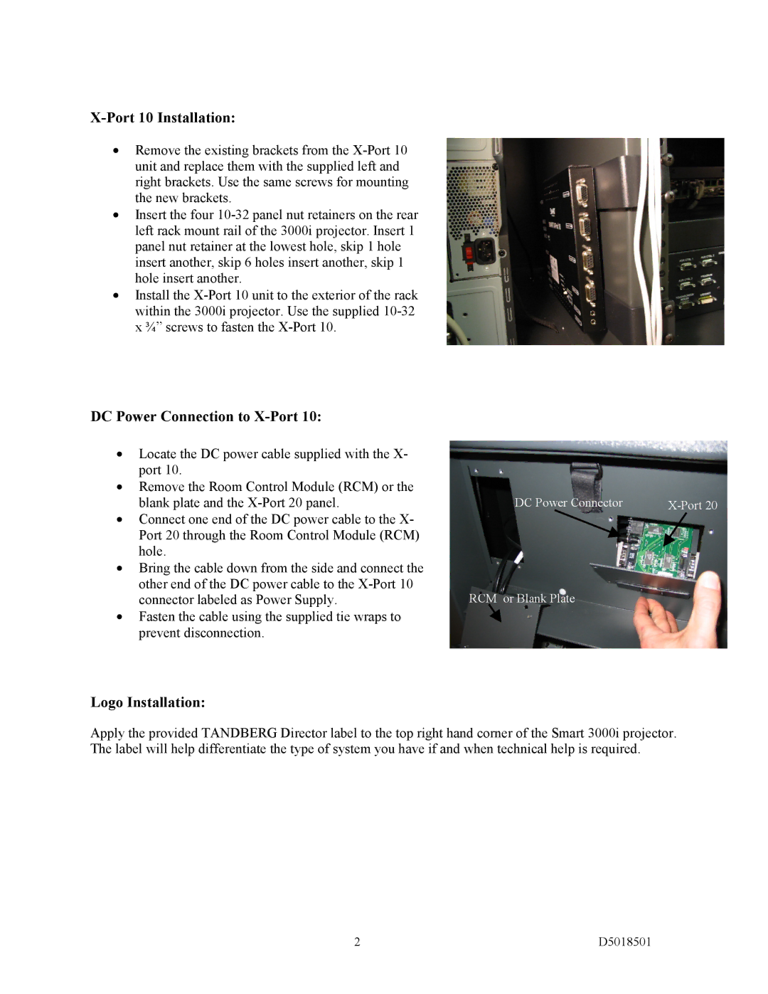
Install the X-Port 10 unit to the exterior of the rack within the 3000i projector. Use the supplied 10-32 x ¾” screws to fasten the X-Port 10.

DC Power Connection to X-Port 10:

Locate the DC power cable supplied with the X- port 10.

Remove the Room Control Module (RCM) or the blank plate and the X-Port 20 panel.

Connect one end of the DC power cable to the X- Port 20 through the Room Control Module (RCM) hole.

Bring the cable down from the side and connect the other end of the DC power cable to the X-Port 10 connector labeled as Power Supply.

Fasten the cable using the supplied tie wraps to prevent disconnection.

DC Power Connector

X-Port 20

RCM or Blank Plate

Logo Installation:

Apply the provided TANDBERG Director label to the top right hand corner of the Smart 3000i projector. The label will help differentiate the type of system you have if and when technical help is required.

2

D5018501

Page 2
Image 2
TANDBERG D5018501 instruction sheet X-Port 10 Installation, DC Power Connection to X-Port, Logo Installation