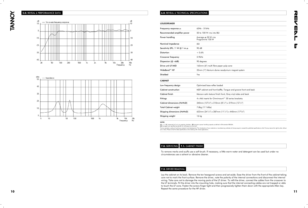
5.0: REVEAL 6 PERFORMANCE DATA
10
6.0: REVEAL 6 TECHNICAL SPECIFICATIONS
LOUDSPEAKER
Frequency response (1) | 63Hz - 51kHz |
|
|
Recommended amplifier power | 50 to 100 W rms into 8Ω |
|
|
Power handling | Average (2) 50 W rms |
| Programme 100 W |
|
|
Nominal Impedance | 6Ω |
|
|
Sensitivity SPL / 1 W @ 1 m (3) | 90 dB |
|
|
Distortion | < 0.6% |
|
|
Crossover frequency | 2.9kHz |
|
|
Dispersion (@ | 90 degrees |
|
|
Drive unit LF/MID | 165mm (6") multi fibre paper pulp cone |
|
|
WideBand™ HF | 25mm (1") titanium dome neodymium magnet system |
|
|
Shielded | Yes |
|
|
|
|
CABINET |
|
|
|
Low frequency design | Optimised |
|
|
Cabinet construction | MDF cabinet and front baffle, Tongue and groove front and back |
|
|
Cabinet finish | Maroon satin texture finish front, Grey vinyl sides and back |
|
|
Fittings | 4 x M6 inserts for Omnimount™ 30 series bracketry |
|
|
Cabinet dimensions (HxWxD) | 340mm (133/8”) x 210mm (81/4”) x 319mm (121/2”) |
|
|
Total Cabinet weight | 7.8kg (17.16lbs) |
|
|
Shipping dimensions (HxWxD) | 622mm (241/2”) x 287mm (111/4”) x 440mm (173/8”) |
|
|
Shipping weight | 16 kg |
|
|
|
|
NOTES
(1)+/- 3 dB, measured at 1m in an anechoic chamber. (2) Long term power handling capacity as defined in EIA standard RS426A.
(3)Averaged over specified bandwidth for
Tannoy operates a policy of continuous research and development. The introduction of new materials or manufacturing methods will always equal or exceed the published specifications which Tannoy reserve the right to alter without prior notice. Please verify the latest specifications when dealing with critical applications.
7.0: SERVICING 
 7.1: CABINET FINISH
To remove marks and scuffs use a soft brush. If necessary, a little warm water and detergent can be used but under no circumstances use a solvent or abrasive cleaner.
7.2: DRIVER REMOVAL
Lay the cabinet on its back. Remove the ten hexagonal screws and set aside. Ease the driver from the front of the cabinet taking care not to mark the front surface. Remove the driver, note the polarity of the internal connections and disconnect the internal wiring. Take care not to damage the moving parts of the LF driver. To refit the driver, connect the cables from the crossover to the LF terminals. Fit the driver into the mounting hole, making sure that the internal connecting cables are not trapped or able to touch the LF cone. Fasten the screws finger tight and then progressively tighten them down with the appropriate Allen key. Repeat the same procedure for the HF driver.
11
