Data Sheet: Veta® iHA48040A033V*, 3.3V/40A Output Half Brick Series
Thermal Performance (continued):
| 40 |
|
|
|
|
|
|
|
| 35 |
|
|
|
|
|
|
|
| 30 |
|
|
|
|
|
|
|
A ) | 25 |
|
|
|
|
|
|
|
r r e n t ( | 20 |
|
|
|
|
|
|
|
p u t C u | 15 |
|
|
|
|
|
|
|
O u t | 10 |
|
|
|
|
|
|
|
|
|
|
|
|
|
|
| |
| 5 |
|
|
|
|
|
|
|
| 0 |
|
|
|
|
|
|
|
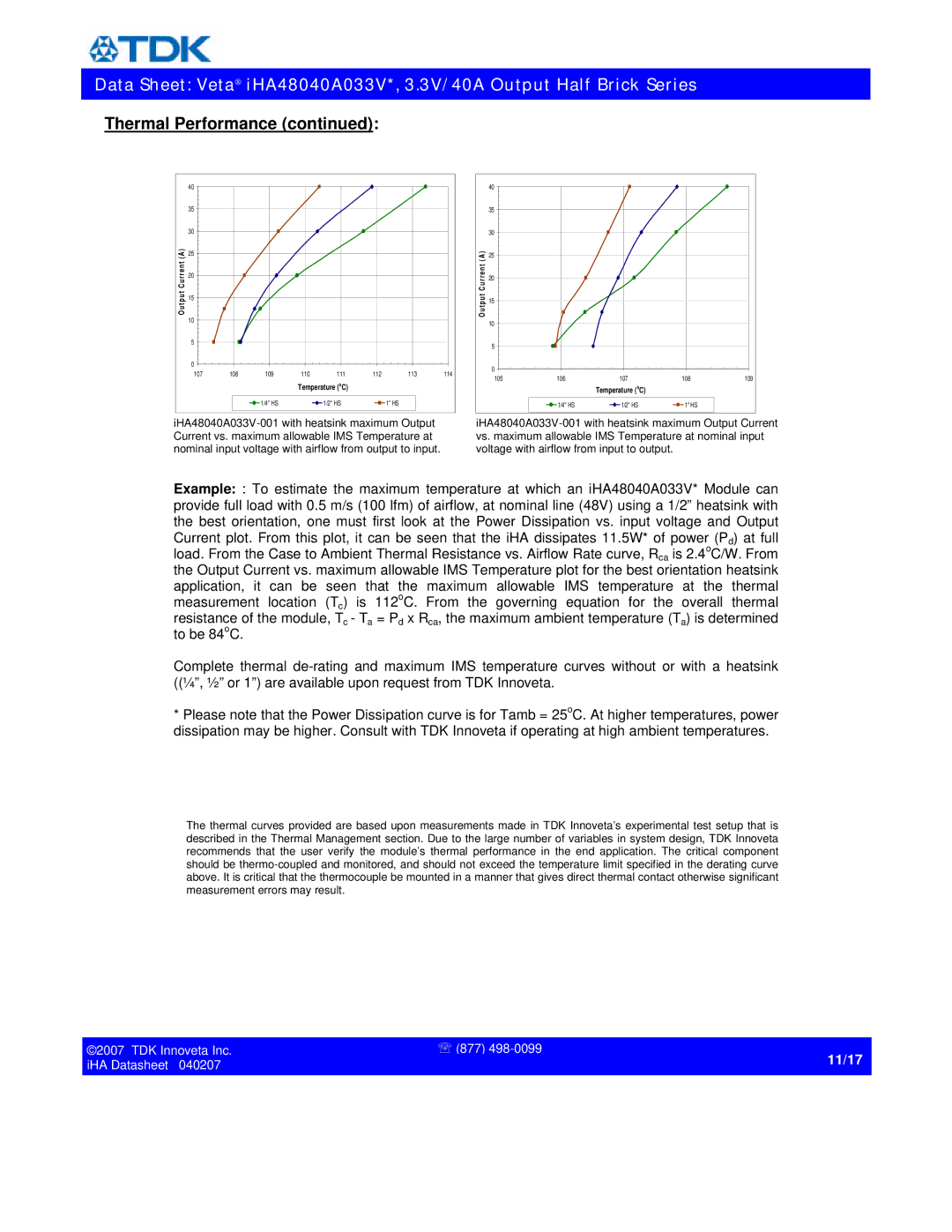
| 107 | 108 | 109 | 110 | 111 | 112 | 113 | 114 |
|
|
|
| Temperature (oC) |
|
|
| |
|
|
| 1/4" HS |
| 1/2" HS |
| 1" HS |
|
| 40 |
|
|
|
|
| 35 |
|
|
|
|
| 30 |
|
|
|
|
A ) | 25 |
|
|
|
|
r r e n t ( | 20 |
|
|
|
|
p u t C u | 15 |
|
|
|
|
O u t | 10 |
|
|
|
|
|
|
|
|
| |
| 5 |
|
|
|
|
| 0 |
|
|
|
|
| 105 | 106 | 107 | 108 | 109 |
|
|
| Temperature (oC) |
|
|
|
| 1/4" HS | 1/2" HS | 1" HS |
|
Example: : To estimate the maximum temperature at which an iHA48040A033V* Module can provide full load with 0.5 m/s (100 lfm) of airflow, at nominal line (48V) using a 1/2” heatsink with the best orientation, one must first look at the Power Dissipation vs. input voltage and Output Current plot. From this plot, it can be seen that the iHA dissipates 11.5W* of power (Pd) at full load. From the Case to Ambient Thermal Resistance vs. Airflow Rate curve, Rca is 2.4oC/W. From the Output Current vs. maximum allowable IMS Temperature plot for the best orientation heatsink application, it can be seen that the maximum allowable IMS temperature at the thermal measurement location (Tc) is 112oC. From the governing equation for the overall thermal resistance of the module, Tc - Ta = Pd x Rca, the maximum ambient temperature (Ta) is determined to be 84oC.
Complete thermal
*Please note that the Power Dissipation curve is for Tamb = 25oC. At higher temperatures, power dissipation may be higher. Consult with TDK Innoveta if operating at high ambient temperatures.
The thermal curves provided are based upon measurements made in TDK Innoveta’s experimental test setup that is described in the Thermal Management section. Due to the large number of variables in system design, TDK Innoveta recommends that the user verify the module’s thermal performance in the end application. The critical component should be
©2007 TDK Innoveta Inc. | ' (877) |
iHA Datasheet 040207 | 11/17 |
| |
|
|