Speakers and FM Antenna | Audio Components |
| DVD To Receiver |
|
|
|
| |||||||||
Speaker | NOTE: | For details, please refer to | Follow the diagram to connect |
|
| Connection described below is also | • After the connections are done, | • If a COAXIAL cable is used to | ||||||||
|
| Instruction manual chapter |
|
| applicable for any component having | check the receiver and make sure it | connect DVD to the receiver, follow | |||||||||
|
| audio components. |
|
| ||||||||||||
• Match the speaker wire color | • The color of the wire should be | “Connecting the Speakers”. |
|
| digital output (Cable, Satellite, MD, | is set to the appropriate input. The | steps 3 to 6 and select COAXIAL. | |||||||||
|
|
|
| |||||||||||||
to the speaker / receiver terminals | the same as that on the terminals. |
|
|
|
|
| CDRW recorder, TV) |
|
| input being used will be displayed |
|
|
|
| ||
as shown on the illustration. | • Connect the striped color wire |
| TV Connections |
| VCR | NOTE: |
|
|
| after the source name. (DVD/OPT |
|
|
|
| ||
• Match the speaker to the | to the |
|
|
|
|
|
| means DVD uses Optical Input) |
|
|
|
|
| |||
correct terminal on the receiver | and receiver) |
| TVs with RF input may need a RF |
| R | • By default, DVD is set to use | • To change input connection, follow |
|
|
|
| |||||
(example: left speaker to left |
|
| modulator (not included) for |
| L | Analog. |
|
|
| step 3 to 6 as described below. |
|
|
|
|
| |
speaker terminal on receiver) |
|
| inputting audio signals. |
|
|
|
|
|
|
|
|
|
|
|
| |
|
|
|
|
|
|
|
|
|
|
|
|
|
|
|
| |
|
|
|
| TV |
|
|
|
|
|
|
|
|
|
|
|
|
Follow the illustration and | SPEAKER | ANTENNA |
|
|
|
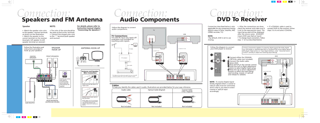
| Follow the diagram to connect | Connect components capable of outputing digital signals like Dolby Digital | ||||||||
instructions provided to |
| RF cable |
| to AUDIO OUT (VCR) | your DVD player to receiver. | (e.g. DVD player or Satelite/Cable Box) or standard PCM format digital signals | ||||||||||
|
|
|
|
|
| |||||||||||
hook up your speakers. |
|
|
| to AUDIO OUT (TV) |
|
|
|
|
| (CD player). Read section on “Input Signal Setting” under “Advanced Sound | ||||||
|
|
|
|
|
|
|
|
| ||||||||
|
|
| RF in | RF out |
| AU |
|
|
|
| Control” carefully to adjust the matching input settings. |
|
|
| ||
|
|
|
|
|
|
|
|
|
|
|
|
|
| |||
|
|
|
|
|
|
| 3 |
|
|
|
|
| DVD |
|
|
|
|
|
|
|
|
|
|
|
| 1 | Connect either the COAXIAL |
|
|
|
| ||
|
|
|
| RF modulator |
|
|
|
|
|
|
|
|
| |||
|
|
|
|
|
|
|
|
| or OPTICAL cable (not included). |
|
|
| (if available) | |||
|
|
|
|
|
|
| 6 | 5 |
| Connect the Audio cable. |
|
|
| COAXIAL | OPTICAL | |
|
|
|
|
|
|
| 2 |
| R |
| OUT | OUT | ||||
|
|
|
| Audio in | IN |
|
| AUDIO |
|
|
| |||||
|
|
|
|
|
|
|
| Select DVD |
| OUT |
|
|
| |||
|
|
|
|
| TV | VCR |
|
| 3 |
| L |
|
|
| ||
|
|
|
|
|
|
|
|
|
|
|
| |||||
|
|
|
| Audio cable |
|
|
|
| 4 Press SETUP on the remote control. |
|
|
|
|
| ||
|
|
|
|
|
|
|
|
| 5 | Press the Left or Right adjustment |
|
|
|
|
| |
|
|
|
| Audio out |
|
| 4 |
| buttons to select Digital Input setup. |
|
|
|
|
| ||
|
|
|
|
|
|
| 6 Press the Up or Down adjustment |
|
| (DVD) |
| (DVD) | ||||
|
|
|
|
|
|
|
|
|
|
|
| |||||
|
| Antenna and Speaker |
|
|
|
|
|
| buttons to select the input being | to AUDIO OUT (DVD) |
| |||||
|
|
|
|
|
|
|
| OUT |
| OUT | ||||||
|
| Wire Connection |
|
|
|
|
|
| used (analog, coaxial, or optical) |
|
|
| ||||
|
| modulator, please refer to your RF modulator manual. |
|
|
|
| 2 |
| COAXIALto |
| OPTICALto | |||||
|
|
|
| AUDIO INPUT |
|
| and release to validate. |
| 1 | |||||||
|
|
| The diagram shown above may varies from your actual RF |
| L |
|
|
|
|
|
| |||||
|
|
|
|
|
|
|
|
|
|
|
|
|
|
|
| |
|
|
|
|
|
| R |
|
| IN |
|
|
| COAXIAL OPTICAL |
DVD | SAT | TV | VCR | CD | TAPE | DIGITAL AUDIO |
|
|
|
|
|
| NOTE: To receive Digital signal |
Push terminal tab down to | Cables |
|
| (Dolby Digital) either a coaxial or |
|
|
|
|
| optical cable must be connected; |
|
| DIGITAL AUDIO | ||
insert wire. |
|
|
|
| |||
| To help you identify the cables used in audio, illustrations are provided below for your easy reference. | and in step 6, you have to select |
|
| COAXIAL OPTICAL | ||
| DVD |
| |||||
| Audio cable | Optical Cable (Digital) | Coaxial Cable | coaxial or optical input |
|
|
|
|
|
| (75Ω / Digital) | accordingly. |
|
|
|
Release tab to lock wire in |
|
|
|
|
|
|
|
the terminal. |
|
|
|
|
| AUDIO INPUT |
|
|
|
|
|
|
|
| |
NOTE: Make sure the insulation |
|
|
|
|
|
| L |
|
|
|
|
|
|
| |
is completely removed from the |
|
|
|
|
|
| R |
ends of the Antenna and |
|
|
|
| IN |
| COAXIAL OPTICAL |
speaker wires at all connection |
|
|
|
| DVD SAT TV | VCR CD TAPE | DIGITAL AUDIO |
points. | Not Included | Not Included | Not Included |
|
|
|
|
|
|
|
|
| |||