Location of Controls and Functions
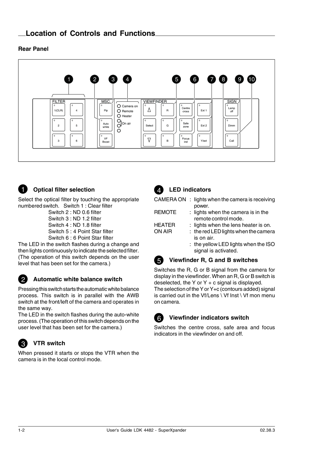
Rear Panel
| 1 | 2 | 3 | 4 |
|
| 5 | 6 | 7 | 8 | 9 | 10 |
FILTER |
|
| MSC. |
| VIEWFINDER |
|
|
|
| SIGN |
| |
0 | 0 |
| 0 | Camera on | 0 | 0 | 0 |
| 0 |
| 0 |
|
|
|
|
|
|
| Centre |
|
|
| Lamp |
| |
1(CLR) |
| 4 | Pip | Remote |
| R |
| Ext 1 |
|
| ||
|
| cross |
|
| off |
| ||||||
|
|
|
| Heater |
|
|
|
|
|
|
|
|
0 | 0 |
| 0 |
| 0 | 0 | 0 |
| 0 |
| 0 |
|
2 |
| 5 | Auto | On air | Select | G | Safe |
| Ext 2 |
| Dimm |
|
| white |
| zone |
|
|
| ||||||
|
|
|
|
|
|
|
|
|
|
| ||
0 | 0 |
| 0 |
| 0 | 0 | 0 |
| 0 |
| 0 |
|
3 |
| 6 | VF |
|
| B | Focus |
| Y/ext |
| Call |
|
| Boost |
|
| ind |
|
|
| |||||
|
|
|
|
|
|
|
|
|
|
| ||
1Optical filter selection
Select the optical filter by touching the appropriate numbered switch. Switch 1 : Clear filter
Switch 2 : ND 0.6 filter
Switch 3 : ND 1.2 filter
Switch 4 : ND 1.8 filter
Switch 5 : 4 Point Star filter
Switch 6 : 6 Point Star filter
The LED in the switch flashes during a change and then lights continuously to indicate the selected filter. (The operation of this switch depends on the user level that has been set for the camera.)
2Automatic white balance switch
Pressing this switch starts the automatic white balance process. This switch is in parallel with the AWB switch at the front/left of the camera and operates in the same way.
The LED in the switch flashes during the
4LED indicators
CAMERA ON | : lights when the camera is receiving |
| power. |
REMOTE | : lights when the camera is in the |
| remote control mode. |
HEATER | : lights when the lens heater is on. |
ON AIR | : the red LED lights when the camera |
| is on air. |
| : the yellow LED lights when the ISO |
| signal is activated. |
5Viewfinder R, G and B switches
Switches the R, G or B signal from the camera for display in the viewfinder. When an R, G or B switch is deselected, the Y or Y + c signal is displayed.
The selection of the Y or Y+c (contours added) signal is carried out in the Vf/Lens \ Vf Inst \ Vf mon menu on camera.
6Viewfinder indicators switch
Switches the centre cross, safe area and focus indicators in the viewfinder on and off.
3VTR switch
When pressed it starts or stops the VTR when the camera is in the local control mode.
User's Guide LDK 4482 - SuperXpander | 02.38.3 |