61401134/329 ingles 18/7/03 16:57 Página 27
Components of a Safety System
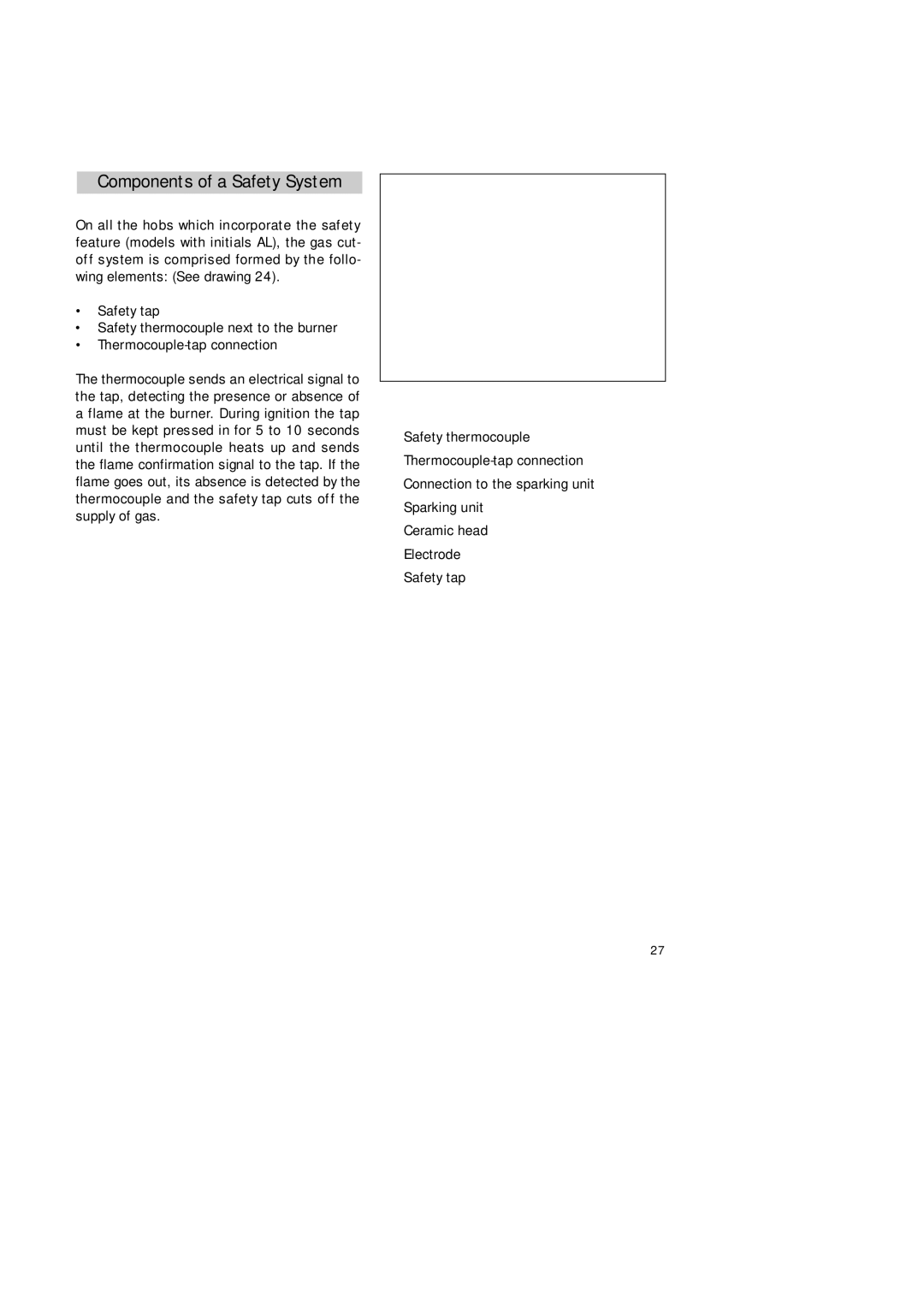
On all the hobs which incorporate the safety feature (models with initials AL), the gas cut- off system is comprised formed by the follo- wing elements: (See drawing 24).
•Safety tap
•Safety thermocouple next to the burner
•
The thermocouple sends an electrical signal to the tap, detecting the presence or absence of a flame at the burner. During ignition the tap must be kept pressed in for 5 to 10 seconds until the thermocouple heats up and sends the flame confirmation signal to the tap. If the flame goes out, its absence is detected by the thermocouple and the safety tap cuts off the supply of gas.
G
C
A | F | |
E | ||
| ||
B | D | |
|
Drawing 24
ASafety thermocouple
B
CConnection to the sparking unit
DSparking unit
ECeramic head
FElectrode G Safety tap
27