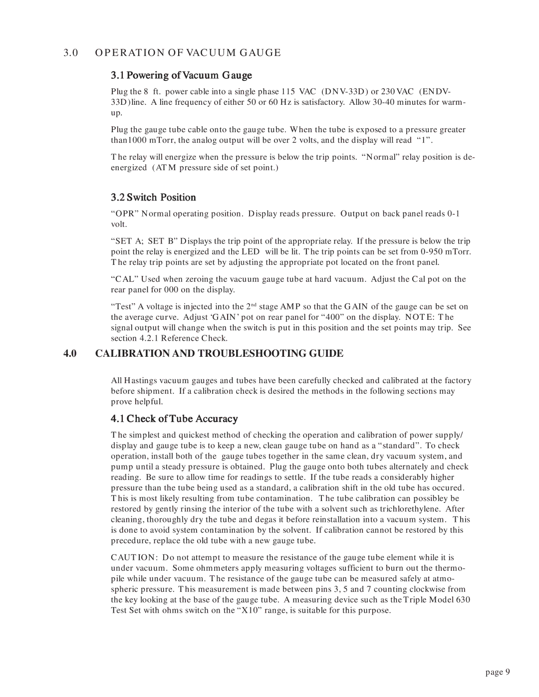
DNV-33D specifications
Teledyne DNV-33D is a cutting-edge underwater monitoring system, designed to deliver high-performance data acquisition and environmental monitoring in various marine settings. Combining advanced technologies with user-friendly interfaces, this system is perfect for applications in oceanography, marine research, and oil and gas exploration.One of the standout features of the Teledyne DNV-33D is its multi-frequency sonar capabilities. This allows the system to capture detailed underwater images and provide precise measurements of both the physical and biological components of the marine environment. With frequencies ranging from low to high, users can tailor their data collection to meet specific project requirements, whether they are examining the seabed or studying aquatic life.
The system is equipped with state-of-the-art signal processing algorithms, enhancing the clarity and resolution of the captured data. These algorithms are essential for filtering out background noise and improving the detection of submerged objects, making it an invaluable tool for marine archaeologists and environmental scientists alike. The DNV-33D also supports real-time monitoring, enabling users to visualize data as it is collected and make instantaneous decisions.
Another key characteristic of the Teledyne DNV-33D is its robust construction, designed to withstand the harsh conditions of underwater environments. Its highly durable housing protects sensitive components from corrosion, pressure, and other potential damages, ensuring reliable operation even in the most challenging marine settings.
The system's portability further enhances its versatility, allowing for easy deployment in various locations, including shallow coastal areas and deep-sea environments. Users can easily transport it on research vessels or deploy it from unmanned underwater vehicles (UUVs), expanding the range of applications.
Additionally, the Teledyne DNV-33D is compatible with an array of sensors and accessories, enabling users to customize their monitoring setup. From temperature and salinity probes to advanced imaging systems, these options allow for a comprehensive assessment of environmental conditions.
In summary, the Teledyne DNV-33D stands out due to its advanced sonar technology, effective signal processing, rugged design, and adaptability. It serves as an essential tool for researchers and engineers aiming to enhance their understanding of underwater ecosystems while ensuring data integrity and accuracy. The system’s wide-ranging capabilities make it a vital asset in the ever-evolving field of marine exploration and monitoring.
