
T200U-NOy specifications
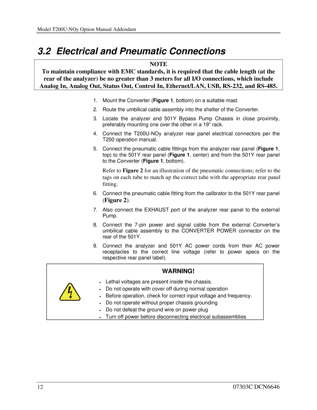
The Teledyne T200U-NOy is an advanced gas analyzer specifically designed to measure nitrogen oxides (NOx) concentrations in a variety of applications, including industrial emissions monitoring, environmental assessments, and combustion control. It builds upon Teledyne's legacy of producing high-quality analytical instruments, making it a reliable choice for professionals in the field.One of the main features of the T200U-NOy is its ability to measure multiple nitrogen oxides, including nitrogen dioxide (NO2), nitric oxide (NO), and nitrous oxide (N2O), which are critical for understanding and managing air quality and combustion efficiency. The instrument offers high sensitivity and accuracy, allowing for real-time monitoring of NOx levels with a detection limit that suits stringent regulatory requirements.
The T200U-NOy utilizes advanced chemiluminescence technology for NO measurement, which is widely recognized for its reliability and precision. This method involves the reaction of NO with ozone (O3) to produce excited NO2, which subsequently releases light as it returns to a lower energy state. The intensity of this light is measured and directly correlates to the concentration of NO in the sample, providing highly accurate readings.
In addition to its core measurement capabilities, the T200U-NOy is equipped with a variety of features that enhance its functionality. Its user-friendly interface allows for easy configuration and data retrieval, making it accessible to a wide range of users, from seasoned professionals to those new to gas analysis. The device supports multiple communication protocols, including analog and digital outputs, facilitating integration into existing monitoring systems.
The T200U-NOy is constructed with robust materials designed to withstand harsh industrial environments, ensuring longevity and reliability. It also includes features for easy maintenance, such as user-replaceable parts, which can significantly reduce downtime.
Overall, the Teledyne T200U-NOy stands out in the field of gas analyzers, combining cutting-edge measurement technologies with user-centric features and robust construction. Its comprehensive capabilities make it an essential tool for accurately monitoring nitrogen oxides, ultimately contributing to better environmental protection and compliance with air quality regulations.