4.3.2 Microphone Jumpers
Depending on which microphone you are us- ing, the following jumpers must be installed:
JP2 - carbon element; JP3 - electret element; JP4 - dynamic element with a low output.
No jumpers are installed for a dynamic micro- phone with a high output.
4.3.3 Receive Line Input Impedance
A 600Ω terminating resistor is provided for each receive line input. Refer to the schematic and Table 1 for the proper jumper installation.
4.3.4 Switch Settings
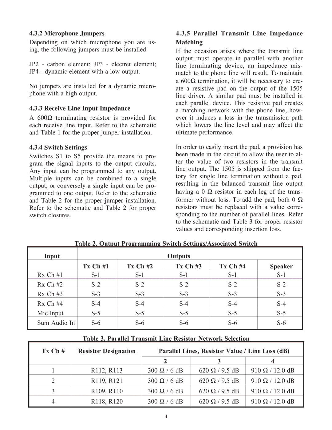
Switches S1 to S5 provide the means to pro- gram the signal inputs to the output circuits. Any input can be programmed to any output. Multiple inputs can be combined to a single output, or conversely a single input can be pro- grammed to one output. Refer to the schematic and Table 2 for the proper jumper installation. Refer to the schematic and Table 2 for proper switch closures.
4.3.5Parallel Transmit Line Impedance Matching
If the occasion arises where the transmit line output must operate in parallel with another line terminating device, an impedance mis- match to the phone line will result. To maintain a 600Ω termination, it will be necessary to cre- ate a resistive pad on the output of the 1505 line driver. A similar pad must be installed in each parallel device. This resistive pad creates a matching network with the phone line, how- ever it induces a loss in the transmission path which lowers the line level and may affect the ultimate performance.
In order to easily insert the pad, a provision has been made in the circuit to allow the user to al- ter the value of two resistors in the transmit line output. The 1505 is shipped from the fac- tory for single line termination without a pad, resulting in the balanced transmit line output having a 0 Ω resistor in each leg of the trans- former without loss. To add the pad, both 0 Ω resistors must be replaced with a value corre- sponding to the number of parallel lines. Refer to the schematic and Table 3 for proper resistor values and corresponding insertion loss.
Table 2. Output Programming Switch Settings/Associated Switch
Input |
|
| Outputs |
|
|
| Tx Ch #1 | Tx Ch #2 | Tx Ch #3 | Tx Ch #4 | Speaker |
Rx Ch #1 | |||||
Rx Ch #2 | |||||
Rx Ch #3 | |||||
Rx Ch #4 | |||||
Mic Input | |||||
Sum Audio In | |||||
|
|
|
|
|
|
Table 3. Parallel Transmit Line Resistor Network Selection
Tx Ch # | Resistor Designation | Parallel Lines, Resistor Value / Line Loss (dB) | ||
|
|
|
|
|
|
| 2 | 3 | 4 |
1 | R112, R113 | 300 Ω / 6 dB | 620 Ω / 9.5 dΒ | 910 Ω / 12.0 dΒ |
2 | R119, R121 | 300 Ω / 6 dB | 620 Ω / 9.5 dΒ | 910 Ω / 12.0 dΒ |
3 | R109, R110 | 300 Ω / 6 dB | 620 Ω / 9.5 dΒ | 910 Ω / 12.0 dΒ |
4 | R118, R120 | 300 Ω / 6 dB | 620 Ω / 9.5 dΒ | 910 Ω / 12.0 dΒ |
|
|
|
|
|
4