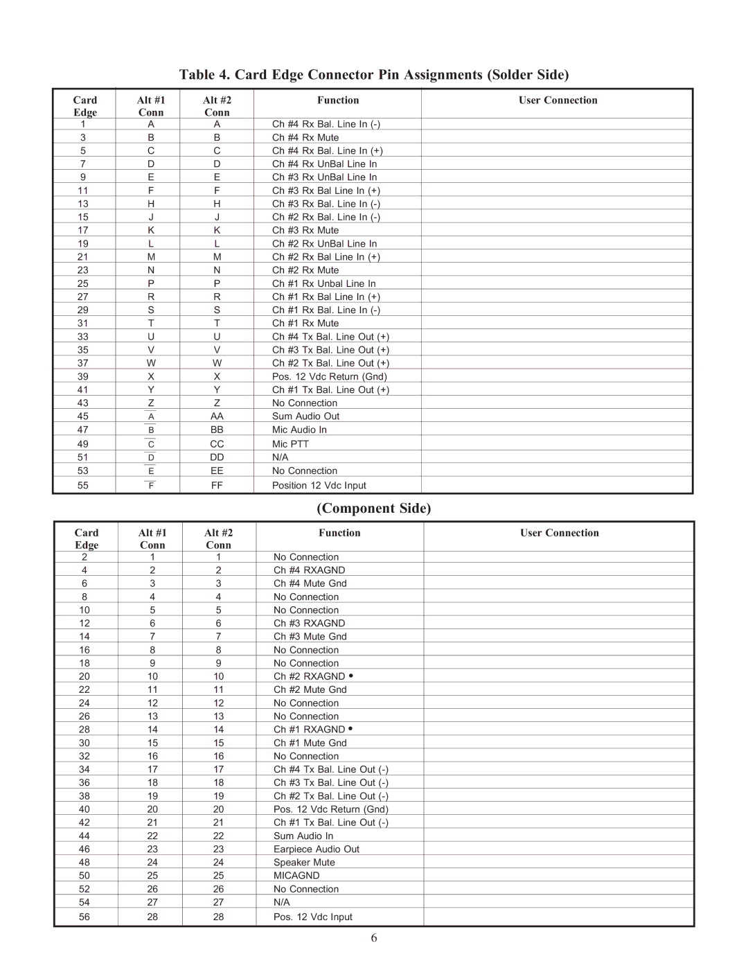
Table 4. Card Edge Connector Pin Assignments (Solder Side)
| Card |
| Alt #1 |
| Alt #2 |
| Function |
|
| User Connection | |||||
| Edge |
| Conn |
| Conn |
|
|
|
|
| |||||
| 1 |
|
| A |
| A |
| Ch #4 Rx Bal. Line In |
|
|
| ||||
| 3 |
|
| B |
| B |
| Ch #4 Rx Mute |
|
|
| ||||
| 5 |
|
| C |
| C |
| Ch #4 Rx Bal. Line In (+) |
|
|
| ||||
| 7 |
|
| D |
| D |
| Ch #4 Rx UnBal Line In |
|
|
| ||||
| 9 |
|
| E |
| E |
| Ch #3 Rx UnBal Line In |
|
|
| ||||
| 11 |
|
| F |
| F |
| Ch #3 Rx Bal Line In (+) |
|
|
| ||||
| 13 |
|
| H |
| H |
| Ch #3 Rx Bal. Line In |
|
|
| ||||
| 15 |
|
| J |
| J |
| Ch #2 Rx Bal. Line In |
|
|
| ||||
| 17 |
|
| K |
| K |
| Ch #3 Rx Mute |
|
|
| ||||
| 19 |
|
| L |
| L |
| Ch #2 Rx UnBal Line In |
|
|
| ||||
| 21 |
|
| M |
| M |
| Ch #2 Rx Bal Line In (+) |
|
|
| ||||
| 23 |
|
| N |
| N |
| Ch #2 Rx Mute |
|
|
| ||||
| 25 |
|
| P |
| P |
| Ch #1 Rx Unbal Line In |
|
|
| ||||
| 27 |
|
| R |
| R |
| Ch #1 Rx Bal Line In (+) |
|
|
| ||||
| 29 |
|
| S |
| S |
| Ch #1 Rx Bal. Line In |
|
|
| ||||
| 31 |
|
| T |
| T |
| Ch #1 Rx Mute |
|
|
| ||||
| 33 |
|
| U |
| U |
| Ch #4 Tx Bal. Line Out (+) |
|
|
| ||||
| 35 |
|
| V |
| V |
| Ch #3 Tx Bal. Line Out (+) |
|
|
| ||||
| 37 |
|
| W |
| W |
| Ch #2 Tx Bal. Line Out (+) |
|
|
| ||||
| 39 |
|
| X |
| X |
| Pos. 12 Vdc Return (Gnd) |
|
|
| ||||
| 41 |
|
| Y |
| Y |
| Ch #1 Tx Bal. Line Out (+) |
|
|
| ||||
| 43 |
|
| Z |
| Z |
| No Connection |
|
|
| ||||
| 45 |
|
|
|
|
|
|
|
| AA |
| Sum Audio Out |
|
|
|
|
|
| A |
|
|
|
|
| |||||||
| 47 |
|
|
|
|
|
| BB |
| Mic Audio In |
|
|
| ||
|
|
| B |
|
|
|
|
| |||||||
| 49 |
|
|
|
|
|
|
| CC |
| Mic PTT |
|
|
| |
|
|
| C |
|
|
|
|
| |||||||
| 51 |
|
|
|
|
|
|
| DD |
| N/A |
|
|
| |
|
|
| D |
|
|
|
|
| |||||||
| 53 |
|
|
|
|
| EE |
| No Connection |
|
|
| |||
|
|
| E |
|
|
|
|
| |||||||
| 55 |
|
|
|
|
|
| FF |
| Position 12 Vdc Input |
|
|
| ||
|
|
| F |
|
|
|
|
| |||||||
|
|
|
|
|
|
|
|
|
|
|
|
|
|
|
|
|
|
|
|
|
|
|
|
|
|
|
| (Component Side) |
| ||
|
|
|
|
|
|
|
|
|
| ||||||
| Card |
| Alt #1 |
| Alt #2 |
| Function |
| User Connection | ||||||
| Edge |
| Conn |
| Conn |
|
|
|
|
| |||||
| 2 |
| 1 |
|
|
|
|
| 1 |
| No Connection |
|
| ||
| 4 |
| 2 |
|
|
|
|
| 2 |
| Ch #4 RXAGND |
|
| ||
| 6 |
| 3 |
|
|
|
|
| 3 |
| Ch #4 Mute Gnd |
|
| ||
| 8 |
| 4 |
|
|
|
|
| 4 |
| No Connection |
|
| ||
| 10 |
| 5 |
|
|
|
|
| 5 |
| No Connection |
|
| ||
| 12 |
| 6 |
|
|
|
|
| 6 |
| Ch #3 RXAGND |
|
| ||
| 14 |
| 7 |
|
|
|
|
| 7 |
| Ch #3 Mute Gnd |
|
| ||
| 16 |
| 8 |
|
|
|
|
| 8 |
| No Connection |
|
| ||
| 18 |
| 9 |
|
|
|
|
| 9 |
| No Connection |
|
| ||
| 20 |
| 10 |
| 10 |
| Ch #2 RXAGND |
|
| ||||||
| 22 |
| 11 |
| 11 |
| Ch #2 Mute Gnd |
|
| ||||||
| 24 |
| 12 |
| 12 |
| No Connection |
|
| ||||||
| 26 |
| 13 |
| 13 |
| No Connection |
|
| ||||||
| 28 |
| 14 |
| 14 |
| Ch #1 RXAGND |
|
| ||||||
| 30 |
| 15 |
| 15 |
| Ch #1 Mute Gnd |
|
| ||||||
| 32 |
| 16 |
| 16 |
| No Connection |
|
| ||||||
| 34 |
| 17 |
| 17 |
| Ch #4 Tx Bal. Line Out |
|
| ||||||
| 36 |
| 18 |
| 18 |
| Ch #3 Tx Bal. Line Out |
|
| ||||||
| 38 |
| 19 |
| 19 |
| Ch #2 Tx Bal. Line Out |
|
| ||||||
| 40 |
| 20 |
| 20 |
| Pos. 12 Vdc Return (Gnd) |
|
| ||||||
| 42 |
| 21 |
| 21 |
| Ch #1 Tx Bal. Line Out |
|
| ||||||
| 44 |
| 22 |
| 22 |
| Sum Audio In |
|
| ||||||
| 46 |
| 23 |
| 23 |
| Earpiece Audio Out |
|
| ||||||
| 48 |
| 24 |
| 24 |
| Speaker Mute |
|
| ||||||
| 50 |
| 25 |
| 25 |
| MICAGND |
|
| ||||||
| 52 |
| 26 |
| 26 |
| No Connection |
|
| ||||||
| 54 |
| 27 |
| 27 |
| N/A |
|
| ||||||
| 56 |
| 28 |
| 28 |
| Pos. 12 Vdc Input |
|
| ||||||
|
|
|
|
|
|
|
|
|
|
|
|
|
|
|
|
6