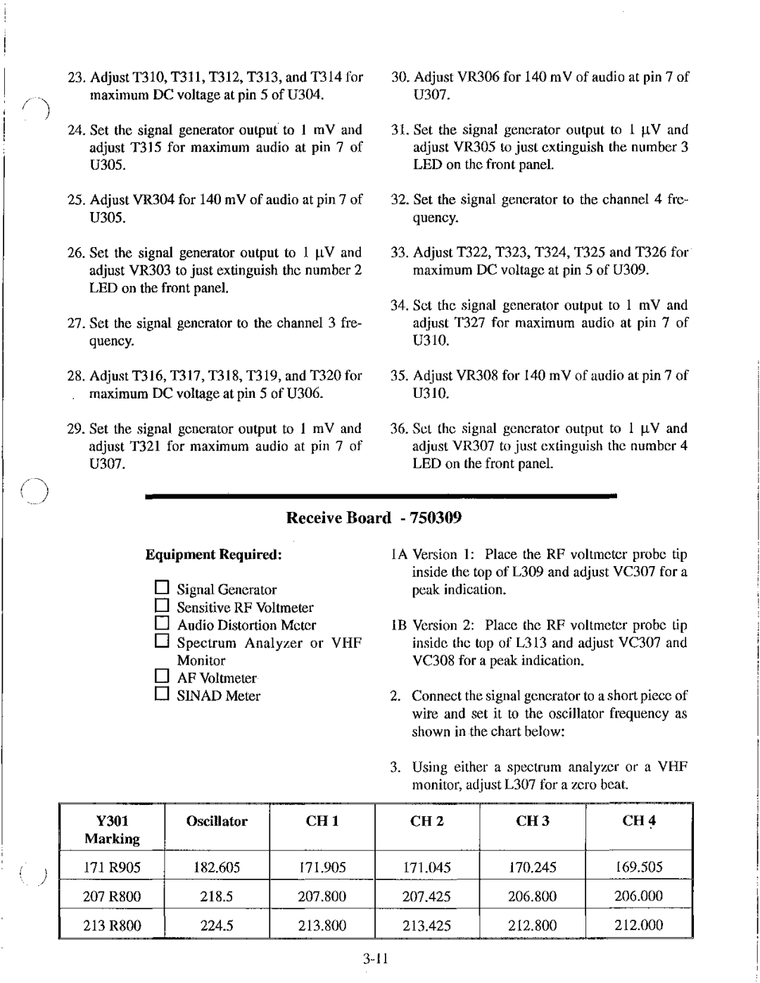
BTR-200 Series specifications
The Telex BTR-200 Series is a well-regarded solution in the realm of wireless intercom systems, widely utilized in broadcast, film, and live event production settings. Renowned for its reliability, user-friendly interface, and robust performance, the BTR-200 Series has become a staple for professionals seeking efficient communication solutions.One of the standout features of the BTR-200 Series is its frequency agility. The system operates in the UHF band, allowing users to switch frequencies to avoid interference from other wireless devices. This adaptability is crucial in environments where multiple wireless systems operate simultaneously. Users can easily reprogram frequencies to ensure clear and uninterrupted communication among team members.
Another key characteristic of the BTR-200 Series is its impressive range. The systems can provide coverage up to 1,000 feet in line-of-sight applications, making it suitable for large venues. This extensive range ensures that communication remains intact even in expansive settings, such as concert halls or outdoor arenas. Additionally, the enhanced RF performance ensures minimal dropouts, contributing to seamless communication.
The BTR-200 Series also distinguishes itself with its digital circuitry, which enhances audio clarity and reduces noise. This reliance on advanced technology results in crisp communication that is essential for coordinating complex productions. The system also features a low-latency design, which is particularly valuable in live performance settings where timing is crucial.
In terms of user interface, the BTR-200 Series is engineered with simplicity in mind. The beltpack units and base station feature intuitive controls that enable quick adjustments, making them easy to operate even under the pressures of a production environment. Each beltpack supports individual volume control, allowing users to customize their audio experience according to their preference.
Moreover, the BTR-200 Series is built for durability and long-lasting operation. The robust construction of its components ensures reliability, even in challenging environments. Rechargeable batteries offer extended operating time while reducing the need for constant replacements.
In summary, the Telex BTR-200 Series stands out for its frequency agility, extensive range, digital audio clarity, user-friendly interface, and durable build quality. These features combined make it an ideal choice for professionals in the broadcasting and live event production industries, promoting seamless and efficient communication essential for successful operations. The BTR-200 Series remains a trusted solution, proving its worth time and again in various high-pressure scenarios.

