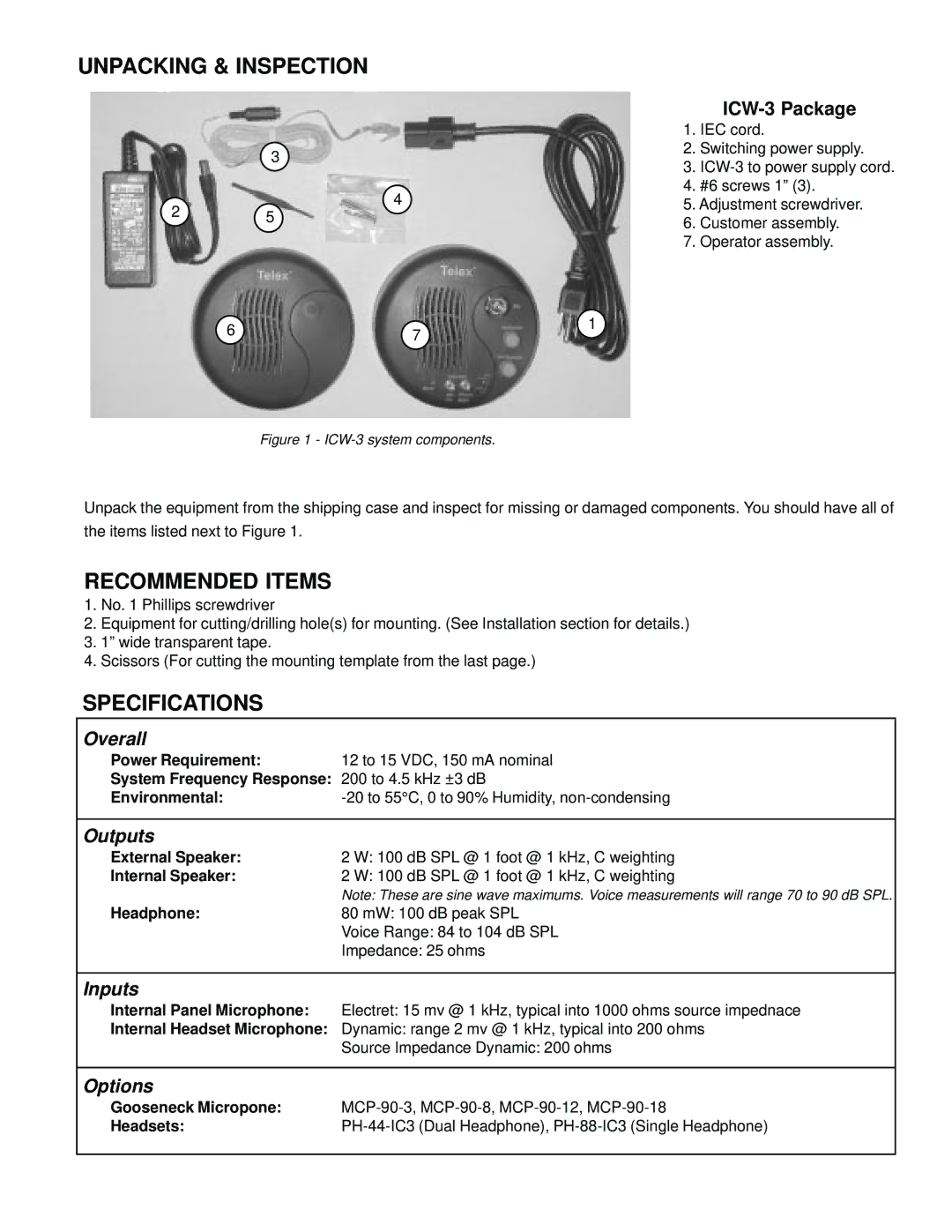
ICW-3 specifications
The Telex ICW-3 wireless intercom system stands out as a versatile communication solution designed for professional audio environments. It is particularly popular in broadcast, theater, and production settings where reliable and clear communication is imperative. The ICW-3 combines advanced wireless technology with user-friendly features, making it a preferred choice among industry professionals.One of the main features of the Telex ICW-3 is its robust wireless performance. Operating on the 2.4 GHz frequency band, the ICW-3 employs digital transmission technology to ensure minimal interference and high-quality audio. This frequency band is less crowded than others often used for wireless communications, allowing for clearer signal transmission over longer distances.
Another significant aspect of the ICW-3 is its flexibility in connectivity. The system supports multiple belt packs, offering a seamless integration into existing intercom setups. Each belt pack can connect wirelessly to a base station, allowing users to communicate with one another without the constraints of traditional wired systems. This wireless capability is particularly beneficial in dynamic environments, enabling physical movement without sacrificing communication quality.
The Telex ICW-3 also features a user-friendly interface, making it easy for operators to navigate through its various functions. With intuitive controls for adjusting microphone sensitivity and audio levels, users can customize their experience to suit specific needs. The system includes a built-in rechargeable battery, providing extended operating time and convenience for users who need to work for hours on end.
In terms of audio quality, the ICW-3 delivers exceptional clarity and low latency, ensuring that conversations sound natural and are easily understood. This is critical in high-pressure environments where miscommunication can lead to costly mistakes. Additionally, the system includes noise-filtering technology that minimizes background noise, further enhancing audio fidelity.
Durability is another hallmark of the Telex ICW-3. Constructed to withstand the rigors of professional use, it features a rugged design that ensures longevity even in challenging conditions. The system is also lightweight and portable, making it easy to transport between locations.
Overall, the Telex ICW-3 wireless intercom system offers a reliable, flexible, and high-quality communication solution for professionals. With its advanced features, user-friendly design, and robust performance, it is well-suited to meet the demanding needs of various audio environments.

