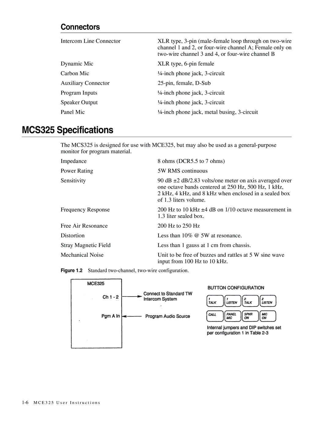
MCE325 specifications
The Telex MCE325 is a sophisticated communications headset designed primarily for professionals who demand clarity and reliability in their audio equipment. Renowned for its advanced features and high-quality construction, the MCE325 is a popular choice in various fields, including aviation, broadcast, and live event production.One of the standout features of the Telex MCE325 is its superior noise-cancellation technology. This headset is engineered to effectively reduce ambient noise, allowing users to focus on important audio signals without distractions. The exceptional passive noise isolation works in tandem with the active noise-cancelling capabilities to ensure that you can communicate clearly, even in loud environments.
The MCE325 also incorporates a high-performance microphone that delivers crystal-clear sound transmission. The flexible boom design allows users to position the microphone for optimal voice pickup, making it suitable for both left- and right-handed users. The microphone’s windscreen further minimizes wind noise, providing an extra layer of clarity during outdoor use.
Comfort is a critical aspect of the MCE325. The headset features plush, padded ear cups that provide excellent comfort for extended use. The adjustable headband ensures a secure fit, catering to a wide range of head sizes and shapes. This ergonomic design minimizes fatigue, allowing users to maintain focus during long hours of operation.
Connectivity is another area where the Telex MCE325 excels. It is versatile enough to work with various devices, thanks to its dual 1/4” and XLR connectors. This flexibility makes it compatible with many audio interfaces and communication systems used in professional settings. The headset also includes a detachable cable, allowing for easy replacement if needed.
The construction of the Telex MCE325 reflects a commitment to durability and longevity. Built with high-quality materials, the headset can withstand the rigors of demanding professional environments. This robustness ensures that users can trust the MCE325 in the most challenging situations, whether it’s in a busy studio or a bustling airport.
In summary, the Telex MCE325 is a versatile and reliable headset designed to meet the needs of professionals across various industries. With its cutting-edge noise-cancellation technology, high-quality microphone, comfort-focused design, versatile connectivity options, and durable construction, it stands out as an ideal choice for anyone seeking superior audio performance and reliability. Whether in communications, aviation, or live broadcasting, the MCE325 delivers an exceptional audio experience.

