| TYPICAL | ||
3 | Pair 1 | 3 | |
2 | 2 | ||
| |||
1 | Pair 2 | 1 (Both wires) | |
Shield |
| Shield | |
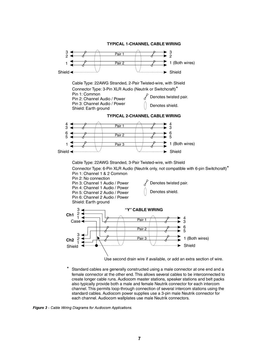
Cable Type: 22AWG Stranded, | ||
Connector Type: | ||
Pin 1: Common | Denotes twisted pair. | |
Pin 2: Channel Audio / Power | ||
| ||
Pin 3: Channel Audio / Power | Denotes shield. | |
Shield: Earth ground | ||
| ||
TYPICAL | ||
4 |
| Pair 1 |
| 4 |
3 |
|
| 3 | |
|
|
| ||
6 |
| Pair 2 |
| 6 |
5 |
|
| 5 | |
|
|
| ||
1 |
| Pair 3 |
| 1 (Both wires) |
Shield |
|
|
| Shield |
Cable Type: 22AWG Stranded, | ||||
Connector Type: | ||||
Pin 1: Channel 1 & 2 Common |
|
| ||
Pin 2: No connection |
|
| Denotes twisted pair. | |
Pin 3: Channel 1 Audio / Power |
| |||
Pin 4: Channel 1 Audio / Power |
| Denotes shield. | ||
Pin 5: Channel 2 Audio / Power |
| |||
Pin 6: Channel 2 Audio / Power |
|
| ||
Shield: Earth ground |
|
|
| |
| 3 | “Y” CABLE WIRING | ||
Ch1 | 2 |
|
| 4 |
| 1 |
| Pair 1 | |
Case |
| 3 | ||
|
| |||
|
|
| Pair 2 | 6 |
|
|
| 5 | |
| 3 |
|
| |
|
| Pair 3 | 1 (Both wires) | |
Ch2 | 2 |
| ||
| 1 |
|
| Shield |
Shield |
|
| ||
Use second drain wire if available, or add an extra section of wire.
*Standard cables are generally constructed using a male connector at one end and a female connector at the other end. This allows several cables to be interconnected to create longer cable runs. Audiocom master stations, speaker stations and belt packs also typically provide both a male and female Neutrik connector for each intercom channel. This permits
Figure 3 - Cable Wiring Diagrams for Audiocom Applications.
7