|
|
| 1 | ||||
|
|
|
|
| |||
|
|
| Power Supply | 2 | |||
|
| Combine / Isolate Switch | “Y” cable | ||||
|
|
| set to Isolate | Y | |||
|
|
|
|
| |||
|
|
|
| SPEAKER | CH 1 | CH 2 |
|
|
|
|
| INPUT 1 |
|
|
|
|
| INPUT 2 |
|
|
| ||
|
|
|
|
|
| ||
| TELEX COMMUNICATIONS, INC. | MADE IN USA | LINE LEVEL | BAL |
|
| |
|
|
|
| 1 VRMS | UNBAL CLASS 2 WIRING 1.5A 24VDC |
| |
| Speaker Inter- |
| 1 |
| 1 |
| |
| connect cable. |
|
|
| |||
|
|
|
|
|
| ||
Program Input |
|
|
| PUSH |
| PUSH | US2000A |
PROGRAM |
|
|
|
|
| Master Station | |
| INPUTS |
|
|
|
|
| |
cable. From 2 |
| LINE LEVEL | 1 | VOL | VOL |
| |
| SPEAKERS |
|
|
|
| ||
+ - | 1 VRMS | 2 | PGM 1 | PGM 2 |
|
| |
audio sources | P.A. | EXP | BAL - OUT |
|
|
|
|
OUT | CHN 1 |
| CHN 2 |
| |||
| UNBAL - IN |
|
| ||||
| To all stations |
|
| To all stations | |||
| on channel 1 |
|
| on channel 2 | |||
| 1 |
|
| 1 | |||
|
|
|
| ||||
HEADSET
LINES | HEADSET |
LINES
BP-1000 1
HEADSET | LINES | HEADSET | LINES |
Y
BP-2000
HEADSET
2
BP-2000
HEADSETLINES
LINES
Note: A
|
| Y |
|
|
|
| |
HEADSET | LINES | HEADSET | LINES |
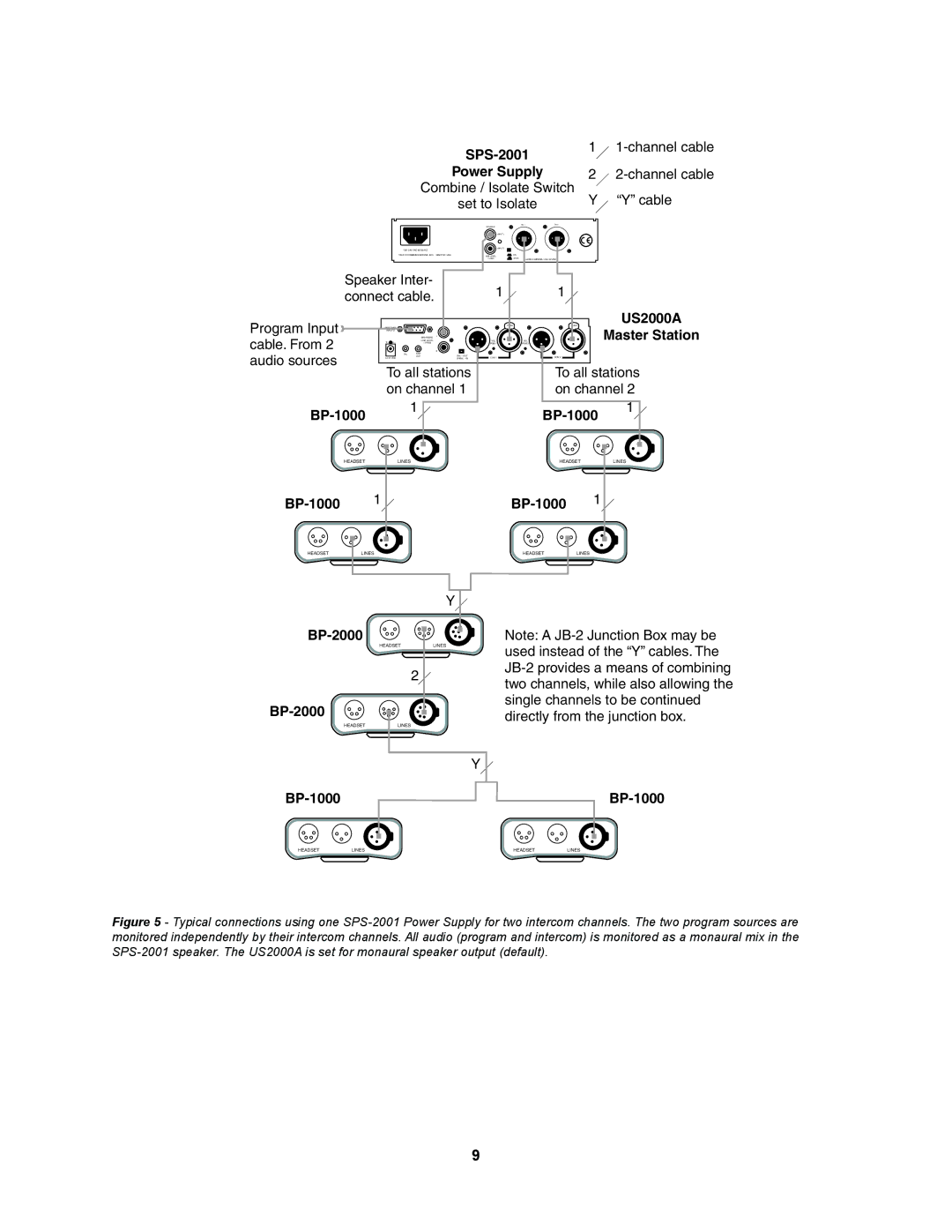
Figure 5 - Typical connections using one SPS-2001 Power Supply for two intercom channels. The two program sources are monitored independently by their intercom channels. All audio (program and intercom) is monitored as a monaural mix in the SPS-2001 speaker. The US2000A is set for monaural speaker output (default).
9