System Configuration
Figure 2 illustrates the typical system configura- tion using the UAD4.
Figure 3 illustrates an arrangement where two splitters have been cascaded. By connecting one of the outputs of the first splitter to the antenna inputs of the second splitter, three additional re- ceivers may be driven by a single pair of anten- nas.
SPECIAL NOTE: In any system, unused split- ter outputs should be terminated with a 50 ohm “dummy load”. See the accessories listing at the end of this manual.
Telex UAD4
UAD4
ANTENNA
POWERSPLITTER
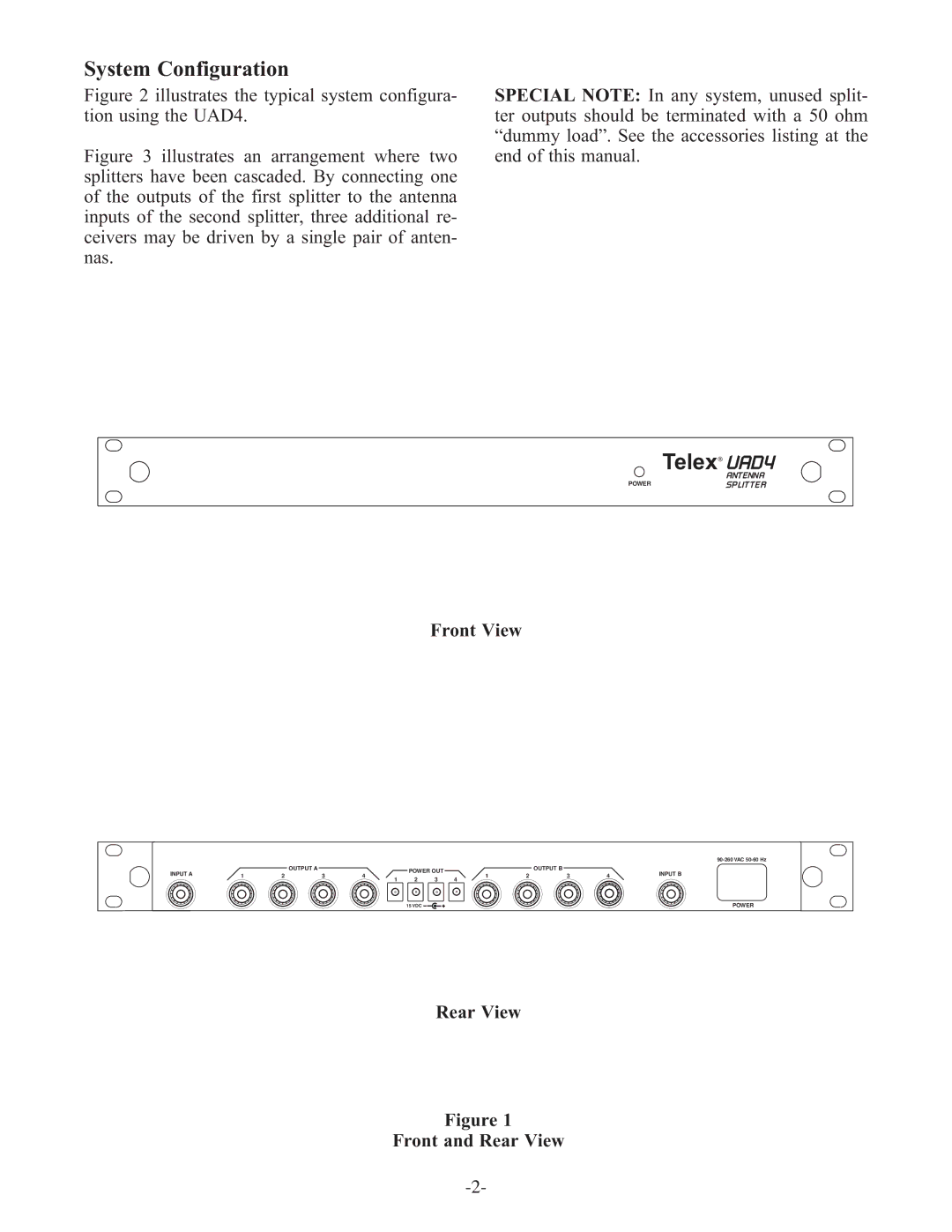
Front View
|
|
|
|
|
|
|
|
|
|
| ||
INPUT A |
|
| OUTPUT A |
| POWER OUT |
|
| OUTPUT B |
| INPUT B | ||
1 | 2 | 3 | 4 | 1 | 2 | 3 | 4 | |||||
2 | 3 | |||||||||||
|
|
|
| 1 | 4 |
|
|
|
| |||
|
|
|
|
| 15 VDC |
|
|
|
|
| POWER | |
Rear View
Figure 1