Smart Digital Adapter
2
Introduction:: (continued)
| Part 2 |
| A2:: |
|
|
| |
|
|
| W3:: |
W1:: |
|
| A1:: |
|
| W2:: | |
|
| A3:: | Part 1 |
|
|
|
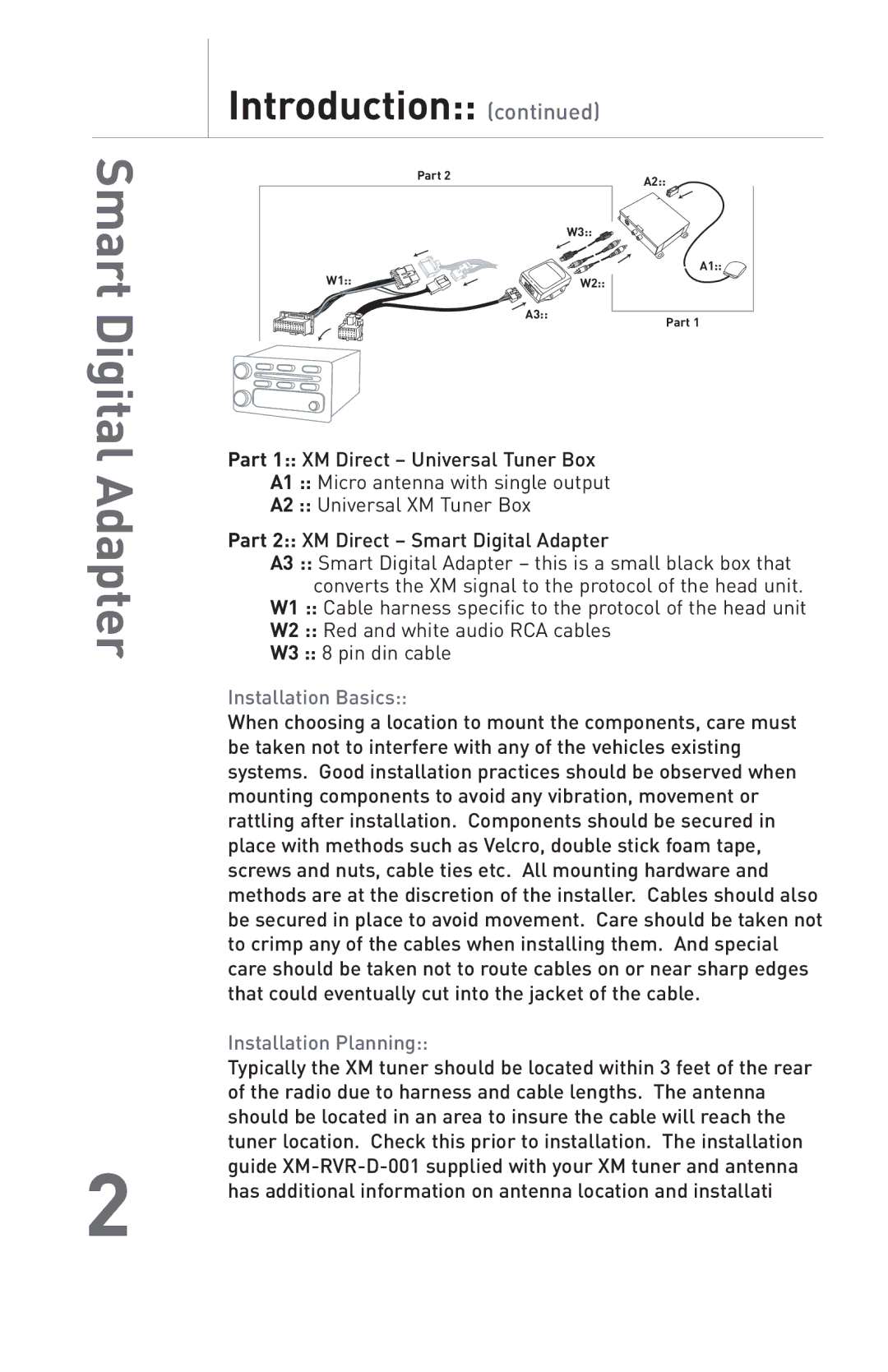
Part 1:: XM Direct – Universal Tuner Box
A1 :: Micro antenna with single output
A2 :: Universal XM Tuner Box
Part 2:: XM Direct – Smart Digital Adapter
A3 :: Smart Digital Adapter – this is a small black box that converts the XM signal to the protocol of the head unit.
W1 :: Cable harness specific to the protocol of the head unit
W2 :: Red and white audio RCA cables
W3 :: 8 pin din cable
Installation Basics::
When choosing a location to mount the components, care must be taken not to interfere with any of the vehicles existing systems. Good installation practices should be observed when mounting components to avoid any vibration, movement or rattling after installation. Components should be secured in place with methods such as Velcro, double stick foam tape, screws and nuts, cable ties etc. All mounting hardware and methods are at the discretion of the installer. Cables should also be secured in place to avoid movement. Care should be taken not to crimp any of the cables when installing them. And special care should be taken not to route cables on or near sharp edges that could eventually cut into the jacket of the cable.
Installation Planning::
Typically the XM tuner should be located within 3 feet of the rear of the radio due to harness and cable lengths. The antenna should be located in an area to insure the cable will reach the tuner location. Check this prior to installation. The installation guide