Manuals
/
Texas Instruments
/
Computer Equipment
/
Computer Hardware
Texas Instruments
DRV8811EVM
manual
Schematic, Step by Step control, Step Control Frame
Models:
DRV8811EVM
1
12
13
13
Download
13 pages
14.95 Kb
6
7
8
9
10
11
12
13
Block Diagram
Signals Frame
power.ti.com
Page 12
Image 12
Page 11
Page 13
Page 12
Image 12
Page 11
Page 13
Contents
Users Guide
DRV8811EVM
SLVA344A-July 2009-Revised September
Submit Documentation Feedback
Contents
List of Figures
VREF SELECT Jumper
DECAY SELECT Jumper
DRV8811RDEVMR1p0.exe Main Screen
Laser and Motor Drives
Users Guide
SLVA344A-July 2009-Revised September
Laser and Motor Drives
1.1 Block Diagram
VM Power
1.2 Power Connectors
1 Introduction
2 Installing Drivers And Software
2.1 Installing the FTDI USB Driver
1.3 Test Stakes
1.4 Jumpers
2.3 Running the Windows Application Software
3 Windows Application
3.2 DRV8811 GPIO Control Signals
Figure 5. Signals Frame
3.1 Menu
Figure 4. Acknowledgement Text Box
VREF=DACVALUE
4095
DECAY=DACVALUE
3.3 Updating DAC Output for Current Control VREF/DECAY
Pulses Per Sec ond
Accel
Time
B ase
4 Schematic
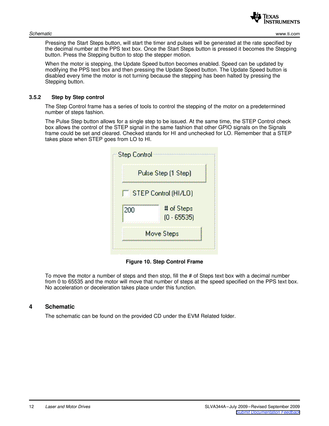
3.5.2 Step by Step control
Figure 10. Step Control Frame
power.ti.com
Products
Applications
amplifier.ti.com
Top
Page
Image
Contents