Manuals
/
Texas Instruments
/
Computer Equipment
/
Computer Hardware
Texas Instruments
DRV8811EVM Test Stakes, Jumpers, Motor Outputs, Installing Drivers And Software
Models:
DRV8811EVM
1
7
13
13
Download
13 pages
14.95 Kb
4
5
6
7
8
9
10
11
Block Diagram
Signals Frame
power.ti.com
Page 7
Image 7
Page 6
Page 8
Page 7
Image 7
Page 6
Page 8
Contents
DRV8811EVM
Users Guide
Submit Documentation Feedback
SLVA344A-July 2009-Revised September
Contents
DRV8811RDEVMR1p0.exe Main Screen
List of Figures
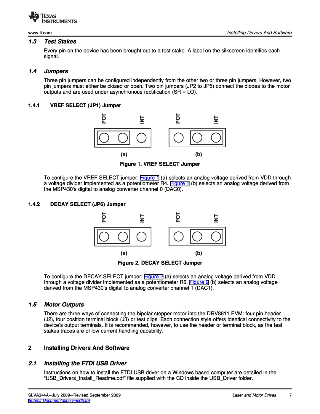
VREF SELECT Jumper
DECAY SELECT Jumper
Laser and Motor Drives
Laser and Motor Drives
Users Guide
SLVA344A-July 2009-Revised September
1 Introduction
1.1 Block Diagram
VM Power
1.2 Power Connectors
1.4 Jumpers
2 Installing Drivers And Software
2.1 Installing the FTDI USB Driver
1.3 Test Stakes
3 Windows Application
2.3 Running the Windows Application Software
Figure 4. Acknowledgement Text Box
3.2 DRV8811 GPIO Control Signals
Figure 5. Signals Frame
3.1 Menu
3.3 Updating DAC Output for Current Control VREF/DECAY
VREF=DACVALUE
4095
DECAY=DACVALUE
B ase
Pulses Per Sec ond
Accel
Time
3.5.2 Step by Step control
4 Schematic
Figure 10. Step Control Frame
amplifier.ti.com
power.ti.com
Products
Applications
Top
Page
Image
Contents