Precautions

2.1 Precautions

Power Supply Input Polarity and Maximum Voltage

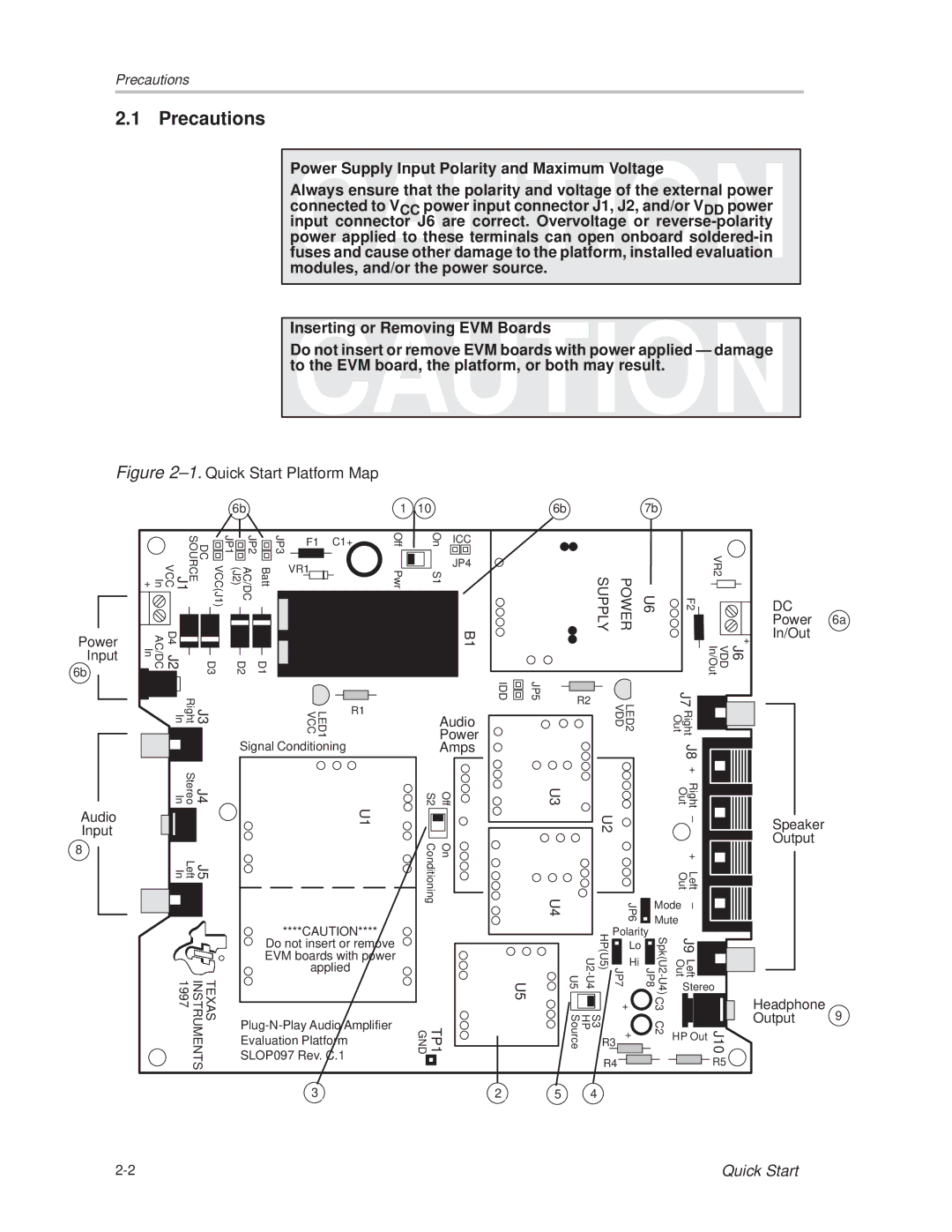
Always ensure that the polarity and voltage of the external power connected to VCC power input connector J1, J2, and/or VDD power input connector J6 are correct. Overvoltage or reverse-polarity power applied to these terminals can open onboard soldered-in fuses and cause other damage to the platform, installed evaluation modules, and/or the power source.

Inserting or Removing EVM Boards

Do not insert or remove EVM boards with power applied Ð damage to the EVM board, the platform, or both may result.

Figure 2±1. Quick Start Platform Map

6b

1

10

6b

7b

Power Input

6b

In +

VCC(J1) DC SOURCE J1 VCC

AC/DC In

D4 J2

D3

JP1


JP2


JP3


F1


C1+

Off


(J2)

AC/DC

Batt


VR1


Pwr


D2

D1


On

ICC


S1

JP4


B1


IDD

JP5

SUPPLY

POWER


VR2

U6

F2

DC


Power 6a


In/Out


+


J6 VDD In/Out

Audio Input

8


Right In

J3


Stereo In

J4


Left In

J5


TEXAS INSTRUMENTS 1997

LED1 VCC

R1


Signal Conditioning


U1

****CAUTION****

Do not insert or remove EVM boards with power applied

Plug-N-Play Audio Amplifier

Evaluation Platform

SLOP097 Rev. C.1

3


Audio


Power


Amps


S2

Off

U3

Conditioning

On

U4

U5

TP1

GND

2 5

R2


LED2 VDD


J7


Right Out


J8


+


Right Out


U2


±


+


Left Out


JP6

Mode

±


Mute


U2-U4 U5

HP(U5)

Polarity


JP7

Lo

Spk(U2-U4) JP8


J9


Hi


Left Out


Stereo

S3 HP Source


+

C3


J10

R3

+

C2

HP Out


R4


R5

4

Speaker

Output

Headphone

Output 9

2-2

Quick Start

Page 12
Image 12
Texas Instruments SLOU025 manual Precautions, Power

SLOU025 specifications

Texas Instruments (TI) is renowned for its extensive portfolio of analog and mixed-signal integrated circuits, with the SLOU025 document detailing a very specific product that focuses on precision applications in various electronics. This document, often referred to in the industry, serves as a comprehensive resource for engineers and designers looking to understand the capabilities of TI's offerings.

One of the main features highlighted in SLOU025 is the high level of precision. The products covered in this document are designed for applications requiring low noise and high accuracy. This characteristic is critical in fields like telecommunications, industrial automation, and medical devices, where even minor inaccuracies can lead to significant system errors.

SLOU025 showcases a range of technologies utilized in TI products, including advanced data conversion techniques. These technologies allow for the seamless integration of multiple functions within a single chip, reducing the overall footprint of electronic designs. This integration not only enhances performance but also simplifies the design process for engineers, enabling faster time-to-market for new products.

Another important characteristic mentioned is power efficiency. Many of the devices described in SLOU025 prioritize low power consumption while maintaining high performance levels. This is particularly important in battery-powered and portable applications, where energy efficiency has a direct impact on the overall usability and lifespan of the device.

The document also emphasizes the versatility of Texas Instruments’ products. With various configurations available, engineers can select the most suitable option for their specific applications, whether it be for automotive, communication, or consumer electronics. This adaptability makes TI components highly sought after in the competitive semiconductor market.

Furthermore, SLOU025 illustrates the commitment of Texas Instruments to continuous innovation. The company invests heavily in research and development to stay at the forefront of technology advancements, which is reflected in the superior performance metrics of its devices.

In summary, Texas Instruments SLOU025 functions as an essential guide for stakeholders involved in electronics design and implementation. It underscores the features of high precision, advanced data conversion technologies, power efficiency, versatility, and a commitment to innovation that collectively enhance TI’s offerings in the market. The detailed insights provided in this document empower engineers to make informed decisions that ultimately lead to the creation of superior electronic solutions.