TMS470R1x specifications
The Texas Instruments TMS470R1x series is an advanced family of microcontrollers designed for automotive and industrial applications, renowned for their robust performance, flexibility, and reliable functionality. Built on a 32-bit RISC architecture, this series provides a powerful computing platform, tailored for embedded control systems.One of the standout features of the TMS470R1x is its high-performance processing capabilities. Operating at clock speeds of up to 120 MHz, these microcontrollers can handle complex calculations and control algorithms efficiently. The TMS470R1x also incorporates a rich set of peripherals, including timers, pulse width modulation (PWM) modules, and communication interfaces like CAN, SPI, and UART. This versatility makes the series suitable for a wide range of applications, from automotive engine control units to industrial automation systems.
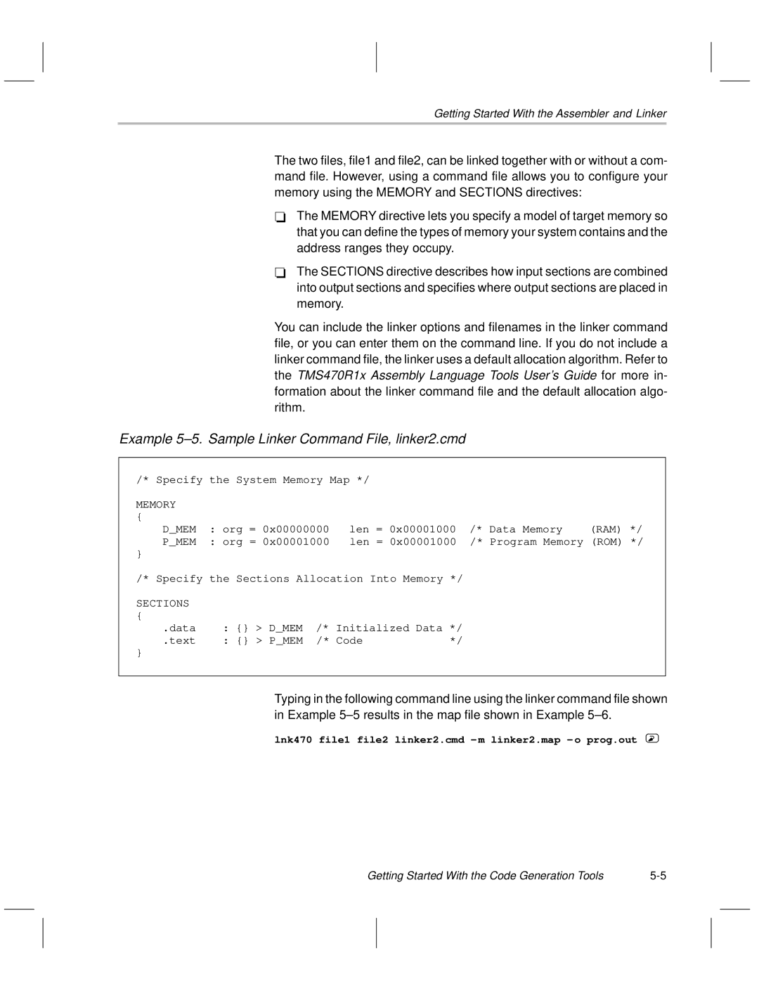
Incorporating advanced memory options, the TMS470R1x features Flash memory sizes ranging from 128 KB to 512 KB, along with RAM ranging from 20 KB to 64 KB. This ample memory is crucial for storing firmware and handling multiple data streams in real time. The microcontrollers also support in-system programming, allowing for easy updates and code modifications during the product lifecycle.
The TMS470R1x series is designed with safety in mind. It adheres to ISO 26262 standards, ensuring high levels of functional safety necessary for automotive systems. Features such as redundancy, error correction, and built-in safety mechanisms ensure operations remain reliable even in fault conditions.
Another important characteristic of the TMS470R1x is its low power consumption, making it ideal for battery-operated devices and equipment. The series employs various power management techniques, including low-power sleep modes, enabling manufacturers to optimize their systems without sacrificing performance.
The integrated Debug and Trace capabilities of the TMS470R1x facilitate effective development and troubleshooting. Engineers can debug their applications in real time, significantly reducing time-to-market and enhancing overall product quality.
In summary, the Texas Instruments TMS470R1x microcontroller series offers a powerful and versatile platform for complex automotive and industrial applications. With its high processing speed, extensive memory options, compliance with safety standards, low power consumption, and robust debugging capabilities, the TMS470R1x is a reliable choice for developers seeking to create innovative and efficient embedded systems. These features combine to position the TMS470R1x series as a leading choice in the expanding field of advanced microcontrollers.

