2.1 Precautions

Power Supply Input Polarity and Maximum Voltage

Always ensure that the polarity and voltage of the external power connected to VCC power input connector J1, J2, and/or VDD power input connector J6 are correct. Overvoltage or reverse-polarity power applied to these terminals can open onboard soldered-in fuses and cause other damage to the platform, installed evaluation modules, and/or the power source.

Inserting or Removing EVM Boards

Do not insert or remove EVM boards with power appliedÐdamage to the EVM board, the platform, or both may result.

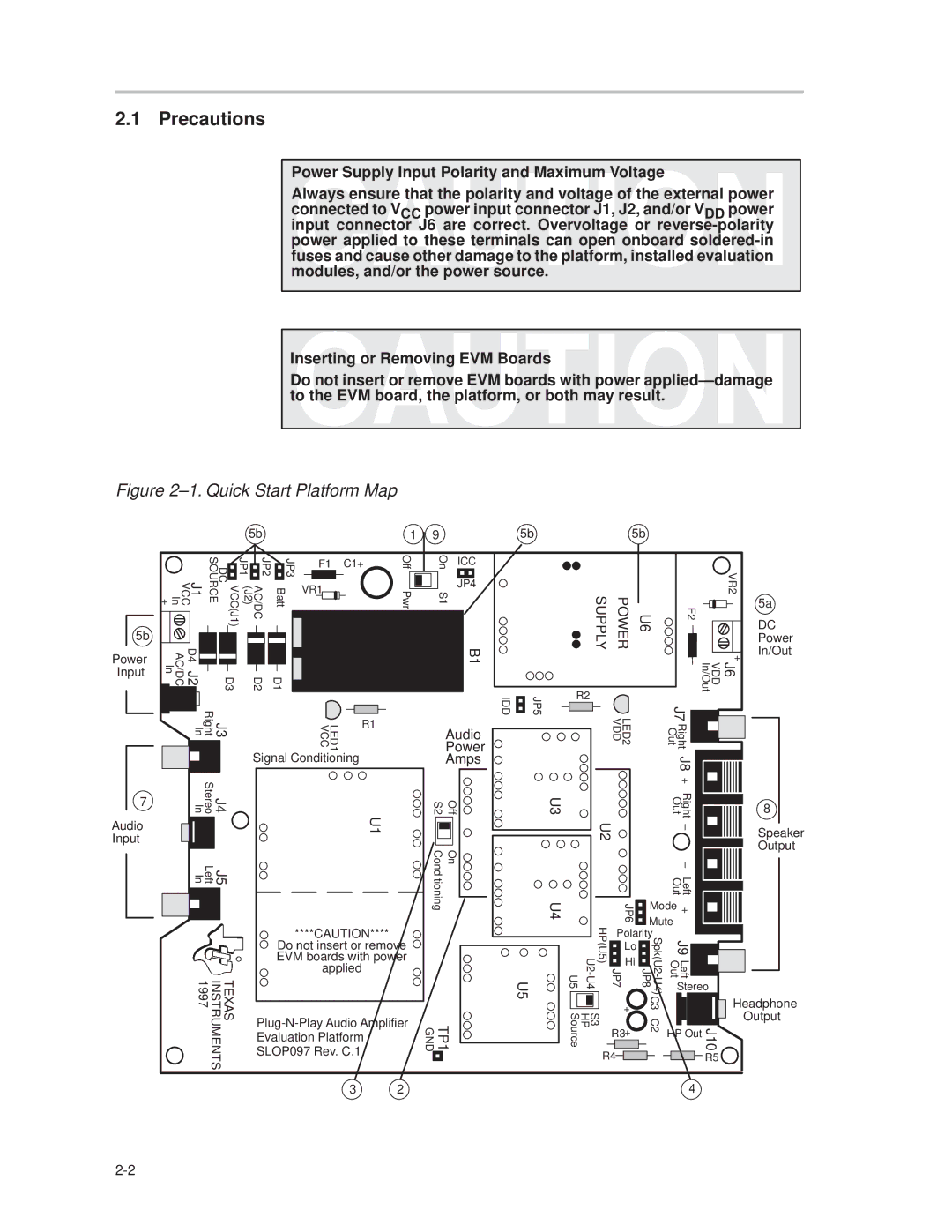
Figure 2±1. Quick Start Platform Map

5b

1

9

5b

5b

5b

Power

Input

J1 VCC In +

VCC(J1) DC SOURCE

(J2)

JP2 AC/DC

JP3 Batt


JP1


F1

C1+


VR1


D4 J2 AC/DC In


D3


D2

D1


J3 Right In


R1


LED1 VCC


Signal Conditioning

Off Pwr

On

ICC


S1

JP4


B1

Audio

Power

Amps

IDD

JP5

R2

SUPPLY

POWER


VR2

U6

F2


+


J6 VDD In/Out


LED2 VDD


J7


Right Out


J8

5a

DC

Power

In/Out

7

Audio Input

J4 J5

Stereo Left

InIn

TEXAS INSTRUMENTS 1997

S2

Off

U1


Conditioning

On

****CAUTION****

Do not insert or remove EVM boards with power applied

Plug-N-Play Audio Amplifier

Evaluation Platform

TP1 GND


SLOP097 Rev. C.1


3

2


U3


U4

U5

U5


Source


+


U2


Right Out


±


±


Left Out


JP6

Mode

+


Mute


U2-U4

JP7 HP(U5)


JP8

Spk(U2-U4)


Polarity


J9


Lo


Hi


Left Out


Stereo

S3 HP

+


C3


J10

R3


C2

HP Out


+


R4


R5


4


8

Speaker

Output

Headphone

Output

2-2

Page 12
Image 12
Texas Instruments TPA0243 manual Precautions, Audio Power Amps

TPA0243 specifications

The Texas Instruments TPA0243 is an advanced class-D audio amplifier that is recognized for its high-performance capabilities and compact design. Specifically designed for portable applications, the TPA0243 delivers impressive sound quality while maximizing energy efficiency. Its compact footprint makes it suitable for a variety of consumer electronics, including mobile devices, tablets, and laptops.

One of the standout features of the TPA0243 is its ability to output up to 3.2 watts of continuous power per channel into a 4-ohm load. This level of power is sufficient for driving small speakers or external audio systems, making it an ideal choice for portable speaker designs. The amplifier also supports operation with a supply voltage range of 2.5V to 5.5V, further enhancing its versatility in different applications.

The TPA0243 utilizes sophisticated technologies to ensure high fidelity audio performance. It includes integrated thermal overload protection and short-circuit protection, which safeguards the device from damage under adverse conditions. Furthermore, the low standby current draw of 2 µA contributes to longer battery life in portable applications, making it energy-efficient.

In addition to its robust performance, the amplifier features low total harmonic distortion (THD) and a signal-to-noise ratio (SNR) of up to 90 dB, ensuring clear audio reproduction. The TPA0243 has a high power supply rejection ratio (PSRR), which helps minimize the impact of power supply variations on audio performance.

The amplifier also supports a variety of output configurations, including stereo and mono options, offering design flexibility for engineers. Its built-in gain setting allows for easy integration into diverse applications, ensuring that it can meet the demands of various output requirements.

Overall, the Texas Instruments TPA0243 stands out as a reliable and versatile audio amplifier, combining compactness with robust performance features. With its integration of advanced technologies, efficient power consumption, and superior sound quality, it is an optimal choice for designers looking to enhance the audio experience in portable electronic devices.