TPA0243 specifications
The Texas Instruments TPA0243 is an advanced class-D audio amplifier that is recognized for its high-performance capabilities and compact design. Specifically designed for portable applications, the TPA0243 delivers impressive sound quality while maximizing energy efficiency. Its compact footprint makes it suitable for a variety of consumer electronics, including mobile devices, tablets, and laptops.One of the standout features of the TPA0243 is its ability to output up to 3.2 watts of continuous power per channel into a 4-ohm load. This level of power is sufficient for driving small speakers or external audio systems, making it an ideal choice for portable speaker designs. The amplifier also supports operation with a supply voltage range of 2.5V to 5.5V, further enhancing its versatility in different applications.
The TPA0243 utilizes sophisticated technologies to ensure high fidelity audio performance. It includes integrated thermal overload protection and short-circuit protection, which safeguards the device from damage under adverse conditions. Furthermore, the low standby current draw of 2 µA contributes to longer battery life in portable applications, making it energy-efficient.
In addition to its robust performance, the amplifier features low total harmonic distortion (THD) and a signal-to-noise ratio (SNR) of up to 90 dB, ensuring clear audio reproduction. The TPA0243 has a high power supply rejection ratio (PSRR), which helps minimize the impact of power supply variations on audio performance.
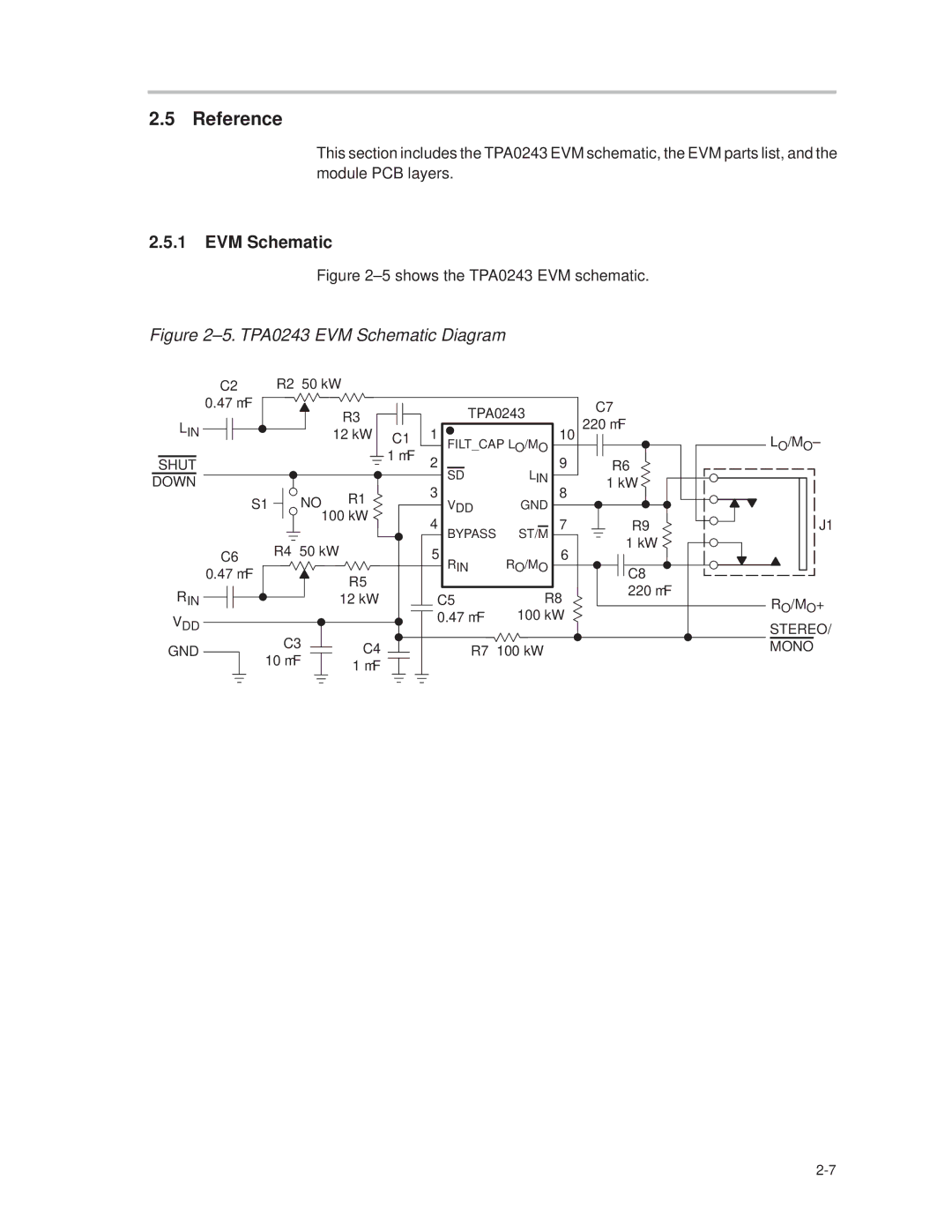
The amplifier also supports a variety of output configurations, including stereo and mono options, offering design flexibility for engineers. Its built-in gain setting allows for easy integration into diverse applications, ensuring that it can meet the demands of various output requirements.
Overall, the Texas Instruments TPA0243 stands out as a reliable and versatile audio amplifier, combining compactness with robust performance features. With its integration of advanced technologies, efficient power consumption, and superior sound quality, it is an optimal choice for designers looking to enhance the audio experience in portable electronic devices.

