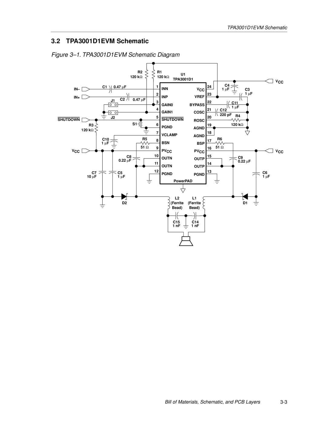
TPA3001D1EVM specifications
The Texas Instruments TPA3001D1EVM is an evaluation module designed to facilitate the analysis and implementation of high-performance audio amplification solutions. This board is a prominent example of Texas Instruments' commitment to offering innovative technologies that cater to both consumer and professional audio applications.One of the more significant features of the TPA3001D1EVM is its efficiency. With the capability to deliver up to 30 Watts per channel into a 4-ohm load, the device utilizes Class-D amplifier technology, which stands out due to its high efficiency. Because it operates with reduced power loss, the TPA3001D1EVM is particularly suited for battery-powered applications, thereby enhancing the operational time without sacrificing audio quality.
The module supports various audio input sources, including differential and single-ended inputs, making it versatile enough to be integrated with a wide range of devices. The built-in I2C interface allows for convenient control over the amplifier’s settings, enabling users to customize the device according to their specific audio requirements. This includes features such as volume control and signal processing enhancements, making it a strong candidate for customization in integrated audio systems.
Another impressive characteristic is the integrated protection features. The TPA3001D1EVM comes equipped with built-in thermal shutdown, short-circuit protection, and over-voltage protection, ensuring that the device can operate safely and reliably in various environmental conditions and under different loads. This reliability is essential for both consumer and professional audio applications, where device failure can lead to increased costs and decreased user satisfaction.
The TPA3001D1EVM is designed with a simplified layout that facilitates easy access to test points, making it user-friendly for engineers and developers testing different configurations. Its compact size further enhances its flexibility for integration into a variety of audio equipment, such as televisions, soundbars, and portable speakers.
In summary, the Texas Instruments TPA3001D1EVM offers a robust suite of features that include high efficiency, versatile inputs, smart control options via I2C, and solid protection mechanisms. Coupled with its user-friendly design, this evaluation module presents an ideal solution for both assessing and developing high-quality audio amplification applications. Whether for professional studio equipment or consumer audio products, the TPA3001D1EVM exemplifies Texas Instruments' dedication to audio excellence.

