Precautions

2.1 Precautions

Power Supply Input Polarity and Maximum Voltage

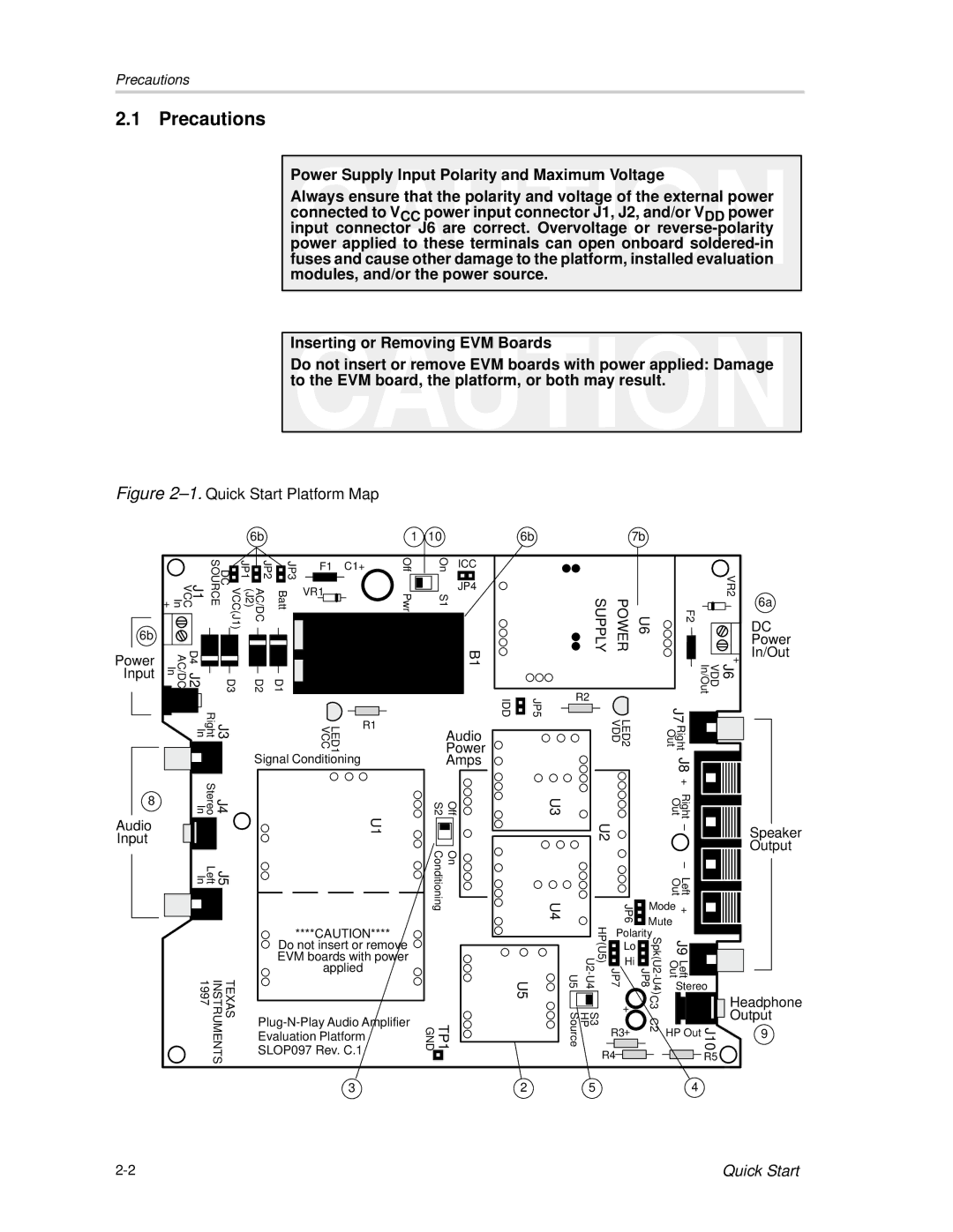
Always ensure that the polarity and voltage of the external power connected to VCC power input connector J1, J2, and/or VDD power input connector J6 are correct. Overvoltage or reverse-polarity power applied to these terminals can open onboard soldered-in fuses and cause other damage to the platform, installed evaluation modules, and/or the power source.

Inserting or Removing EVM Boards

Do not insert or remove EVM boards with power applied: Damage to the EVM board, the platform, or both may result.

Figure 2–1.Quick Start Platform Map

6b

1

10

6b

7b

6b

Power Input

J1 VCC In +

VCC(J1) DC SOURCE

(J2)

JP2 AC/DC

JP3 Batt


JP1


F1

C1+


VR1


D4 J2 AC/DC In


D3


D2

D1


J3 Right In


R1


LED1 VCC


Signal Conditioning

Off Pwr

On

ICC


S1

JP4


B1

Audio

Power

Amps

IDD

JP5

R2

SUPPLY

POWER


VR2

U6

F2


+


J6 VDD In/Out


LED2 VDD


J7


Right Out


J8

6a

DC

Power

In/Out

8

Audio Input

J4 J5

Stereo Left

InIn

TEXAS INSTRUMENTS 1997

S2

Off

U1


Conditioning

On

****CAUTION****

Do not insert or remove EVM boards with power applied

Plug-N-Play Audio Amplifier

TP1 GND

Evaluation Platform


SLOP097 Rev. C.1


3


+


U3


U2


Right Out


Left Out


U4


JP6

Mode

+


JP7 HP(U5)

Mute


U5

U5

U2-U4

+


C3 JP8


Polarity

J9 Left Out


Lo

Spk(U2 -


Hi

U4)


Stereo


S3 HP Source

R3

C2

HP Out

J10


+


R4


R5

2


5


4


Speaker

Output

Headphone Output

9

2-2

Quick Start

Page 12
Image 12
Texas Instruments TPA6102A2 manual Precautions, Power

TPA6102A2 specifications

The Texas Instruments TPA6102A2 is a high-performance audio amplifier designed specifically for driving headphones and providing enhanced audio quality. This device is well-regarded for its ability to deliver superior sound output with a focus on low power consumption, making it an ideal choice for portable audio applications.

One of the main features of the TPA6102A2 is its ability to support a wide supply voltage range, functioning effectively from 2.0 V to 5.5 V. This allows it to be used across various devices, from simple battery-operated systems to more complex multi-voltage applications. Additionally, the amplifier is designed to deliver an output power of up to 50 mW into a 16-ohm load, making it suitable for driving a range of headphones without distortion or loss of audio fidelity.

The TPA6102A2 incorporates advanced technologies, including a unique low-noise architecture that minimizes background interference and enhances signal clarity. This architecture contributes to a high signal-to-noise ratio (SNR) of up to 90 dB, ensuring that users experience clear and crisp audio across various frequency ranges. Furthermore, its total harmonic distortion plus noise (THD+N) is remarkably low, typically around 0.03%, ensuring that audio playback maintains its integrity and high quality.

Another significant characteristic of the TPA6102A2 is its thermal protection and internal short-circuit protection features, which safeguard the device from damage during operation. This reliability enhances the performance of the amplifier in demanding applications, ensuring longevity and consistent operation under varying conditions.

The TPA6102A2 is also designed with a wide range of applications in mind, from mobile phones and tablets to laptops and audio equipment. Its compact package size helps save board space, making it easy to integrate into a variety of designs without compromising performance. Additionally, the amplifier is known for its low quiescent current, which conserves battery life in portable systems, adding to its appeal for manufacturers targeting energy-efficient designs.

In summary, the Texas Instruments TPA6102A2 is a versatile and efficient audio amplifier that combines high-quality sound performance with robust features and compact design. Its specification and suitability for various applications make it a preferred choice for engineers and designers looking to implement superior audio capabilities into their products.