
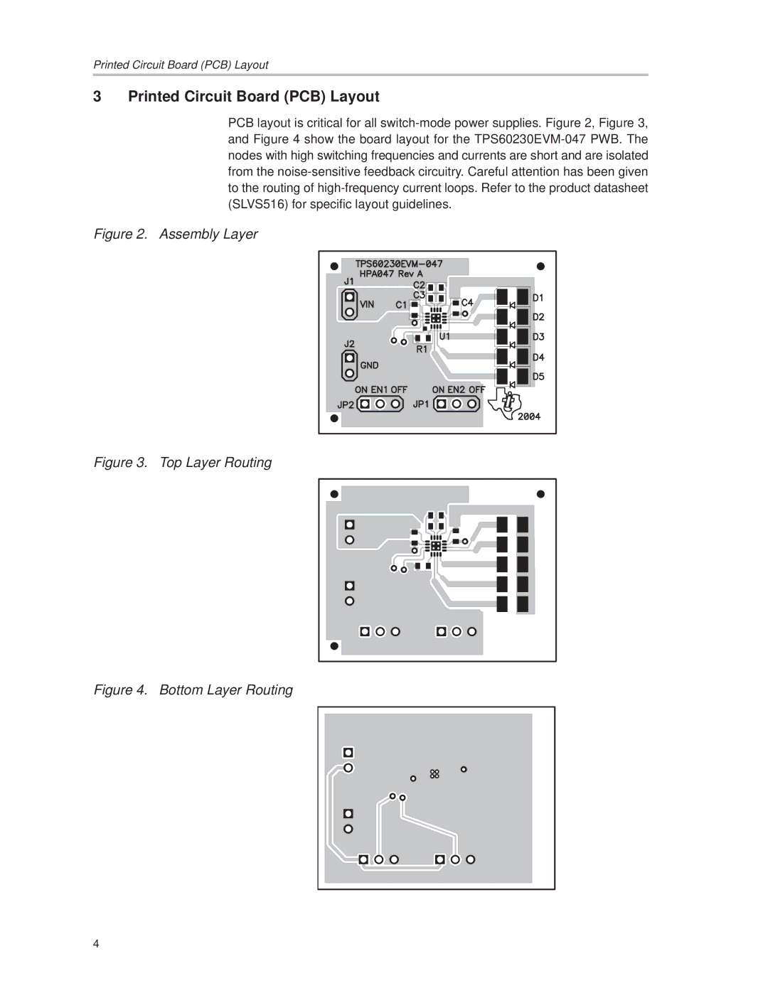
TPS60230EVM-047 specifications
The Texas Instruments TPS60230EVM-047 Evaluation Module is a versatile platform designed to facilitate the evaluation and application of the TPS60230 high-efficiency boost converter. Targeted for applications demanding reliable power solutions, the TPS60230EVM-047 is ideal for LED drivers, portable devices, and battery-operated systems where efficiency is paramount.One of the standout features of the TPS60230 is its ability to deliver a maximum output current of 1A while operating from a wide input voltage range of 1.8V to 5.5V. This flexibility allows the device to be powered by various types of battery sources, making it suitable for a wide range of applications. Its ability to provide a regulated and stable output voltage makes it an excellent choice for situations where consistent performance is crucial.
The module utilizes an innovative control scheme, which contributes to its high efficiency, often exceeding 90%. This makes the TPS60230 particularly advantageous in applications where battery life is critical. The device employs a boost topology, enabling it to step up lower voltages to higher output levels, thereby maximizing the usability of available power sources.
In terms of design, the TPS60230EVM-047 features a compact layout that allows for easy integration into existing systems. The evaluation module includes all necessary components for testing and evaluation, including the TPS60230 IC, inductor, capacitors, and feedback resistors. This comprehensive design aids engineers in quickly prototyping and validating their power solutions.
Another notable characteristic of the TPS60230 is its built-in thermal protection and over-current protection features, which enhance reliability and safeguard against overheating and excessive current conditions. Additionally, the device supports adjustable output voltage settings via external resistors, allowing users to customize their output per specific application requirements.
Furthermore, the device operates at a frequency of up to 1.2MHz, which not only supports smaller passive components but also minimizes PCB space requirements. This compact footprint is essential for modern electronic designs where space conservation is a priority.
To sum up, the Texas Instruments TPS60230EVM-047 Evaluation Module provides a comprehensive solution for evaluating a high-performance boost converter. Its blend of efficiency, versatility, and user-friendly design makes it an excellent choice for engineers aiming to develop efficient power solutions. With its robust feature set and advanced characteristics, the TPS60230EVM-047 stands out as a key component in the realm of power management.