www.ti.com
Board Layout
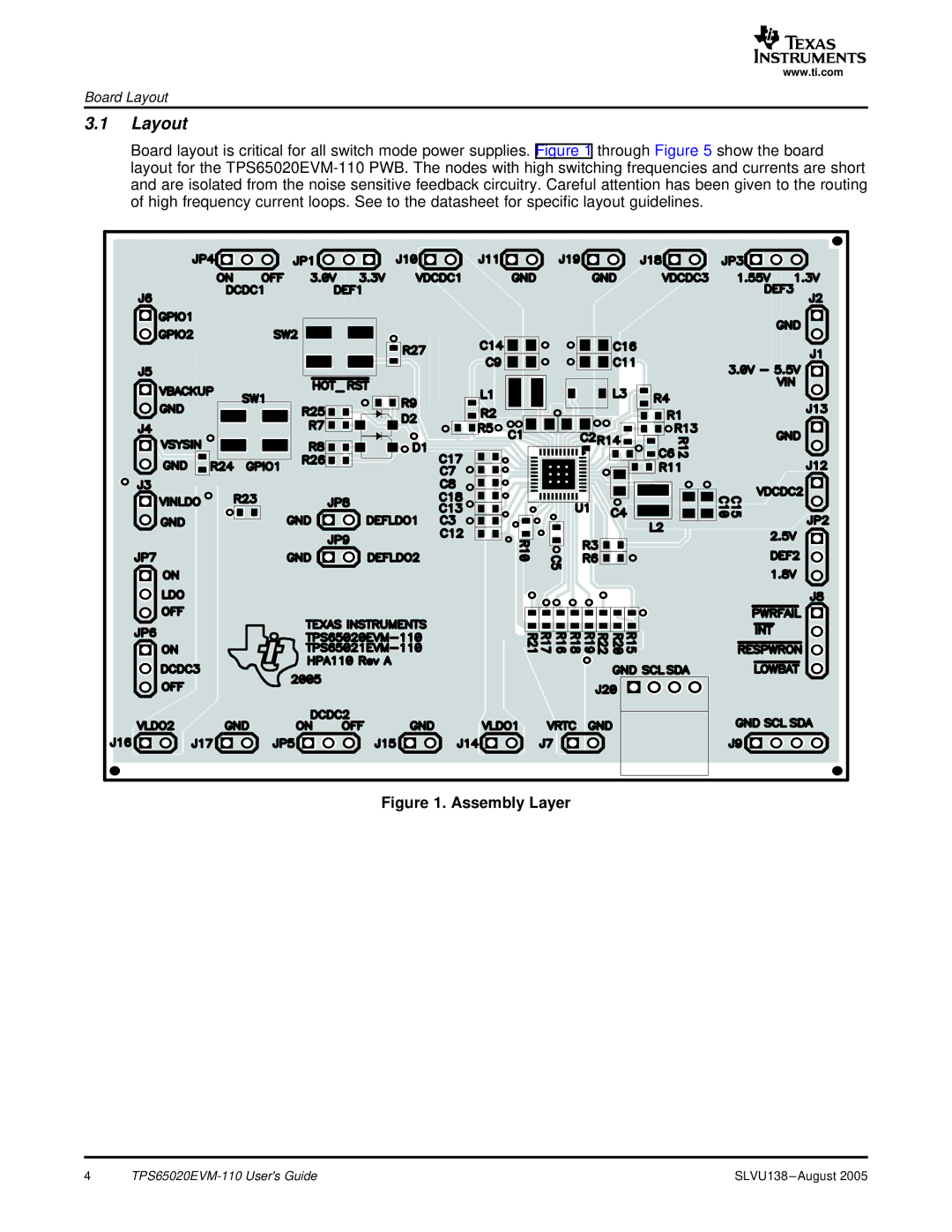
3.1Layout
Board layout is critical for all switch mode power supplies. Figure 1 through Figure 5 show the board layout for the
Figure 1. Assembly Layer
4 | SLVU138 |
www.ti.com
Board Layout
Board layout is critical for all switch mode power supplies. Figure 1 through Figure 5 show the board layout for the
4 | SLVU138 |