VCC Software in Depthwww.ti.com


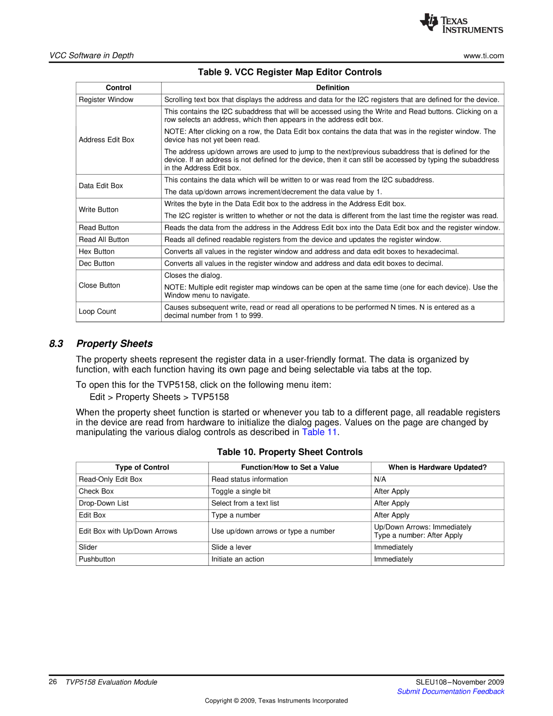
Table 9. VCC Register Map Editor Controls


Control

Definition


Register Window

Scrolling text box that displays the address and data for the I2C registers that are defined for the device.


This contains the I2C subaddress that will be accessed using the Write and Read buttons. Clicking on a


row selects an address, which then appears in the address edit box.


NOTE: After clicking on a row, the Data Edit box contains the data that was in the register window. The

Address Edit Box

device has not yet been read.


The address up/down arrows are used to jump to the next/previous subaddress that is defined for the


device. If an address is not defined for the device, then it can still be accessed by typing the subaddress


in the Address Edit box.


Data Edit Box

This contains the data which will be written to or was read from the I2C subaddress.

The data up/down arrows increment/decrement the data value by 1.


Write Button

Writes the byte in the Data Edit box to the address in the Address Edit box.

The I2C register is written to whether or not the data is different from the last time the register was read.


Read Button

Reads the data from the address in the Address Edit box into the Data Edit box and the register window.


Read All Button

Reads all defined readable registers from the device and updates the register window.


Hex Button

Converts all values in the register window and address and data edit boxes to hexadecimal.


Dec Button

Converts all values in the register window and address and data edit boxes to decimal.


Closes the dialog.

Close Button

NOTE: Multiple edit register map windows can be open at the same time (one for each device). Use the


Window menu to navigate.


Loop Count

Causes subsequent write, read or read all operations to be performed N times. N is entered as a

decimal number from 1 to 999.


8.3Property Sheets

The property sheets represent the register data in a user-friendly format. The data is organized by function, with each function having its own page and being selectable via tabs at the top.

To open this for the TVP5158, click on the following menu item: Edit > Property Sheets > TVP5158

When the property sheet function is started or whenever you tab to a different page, all readable registers in the device are read from hardware to initialize the dialog pages. Values on the page are changed by manipulating the various dialog controls as described in Table 11.

Table 10. Property Sheet Controls

Type of Control

Function/How to Set a Value

When is Hardware Updated?


Read-Only Edit Box

Read status information

N/A


Check Box

Toggle a single bit

After Apply


Drop-Down List

Select from a text list

After Apply


Edit Box

Type a number

After Apply


Edit Box with Up/Down Arrows

Use up/down arrows or type a number

Up/Down Arrows: Immediately

Type a number: After Apply


Slider

Slide a lever

Immediately


Pushbutton

Initiate an action

Immediately


26 TVP5158 Evaluation Module

SLEU108 –November 2009


Submit Documentation Feedback

Copyright © 2009, Texas Instruments Incorporated

Page 26
Image 26
Texas Instruments TVP5158 Property Sheets, VCC Register Map Editor Controls, Property Sheet Controls, Control Definition

TVP5158 specifications

The Texas Instruments TVP5158 is a highly versatile and efficient video decoder designed for a range of video processing applications. It serves as an excellent solution for converting analog video signals into digital formats for further processing. The device is commonly utilized in surveillance systems, video conferencing equipment, and various multimedia applications where reliable and high-quality video output is necessary.

One of the primary features of the TVP5158 is its ability to accept multiple video formats, including NTSC, PAL, and SECAM. This flexibility makes it suitable for a global market where different standards are employed. The device can handle up to four composite video inputs, allowing users to connect multiple sources and switch between them as needed seamlessly. The integrated multiplexing capability makes the TVP5158 an excellent choice for applications that require real-time processing of various video sources.

The TVP5158 also incorporates advanced noise reduction technology, which enhances the quality of the output video by minimizing artifacts and disturbances that may affect the viewing experience. This feature is particularly beneficial in situations where video signals may be degraded due to environmental factors. Additionally, the chip includes capabilities for automatic gain control, which helps adjust the signal levels to maintain consistent output quality.

Another significant characteristic of the TVP5158 is its built-in color space conversion. The device can transform the incoming video signals from YCbCr to RGB or vice versa, ensuring compatibility with a wide range of display systems and digital video formats. This feature is essential for applications that work with various video standards and require high fidelity in color representation.

The TVP5158 is designed for low power consumption, making it ideal for battery-operated devices and systems where energy efficiency is crucial. Its small footprint and integration capabilities also allow for easier design and implementation within existing systems without requiring extensive space or additional components.

In summary, the Texas Instruments TVP5158 is a robust video decoder that offers a rich set of features, including support for multiple video formats, advanced noise reduction, automatic gain control, and color space conversion. Its low power requirements and compact design make it an attractive choice for a variety of applications, positioning it as a reliable solution for modern video processing needs.