S210® Wiring Block Instructions
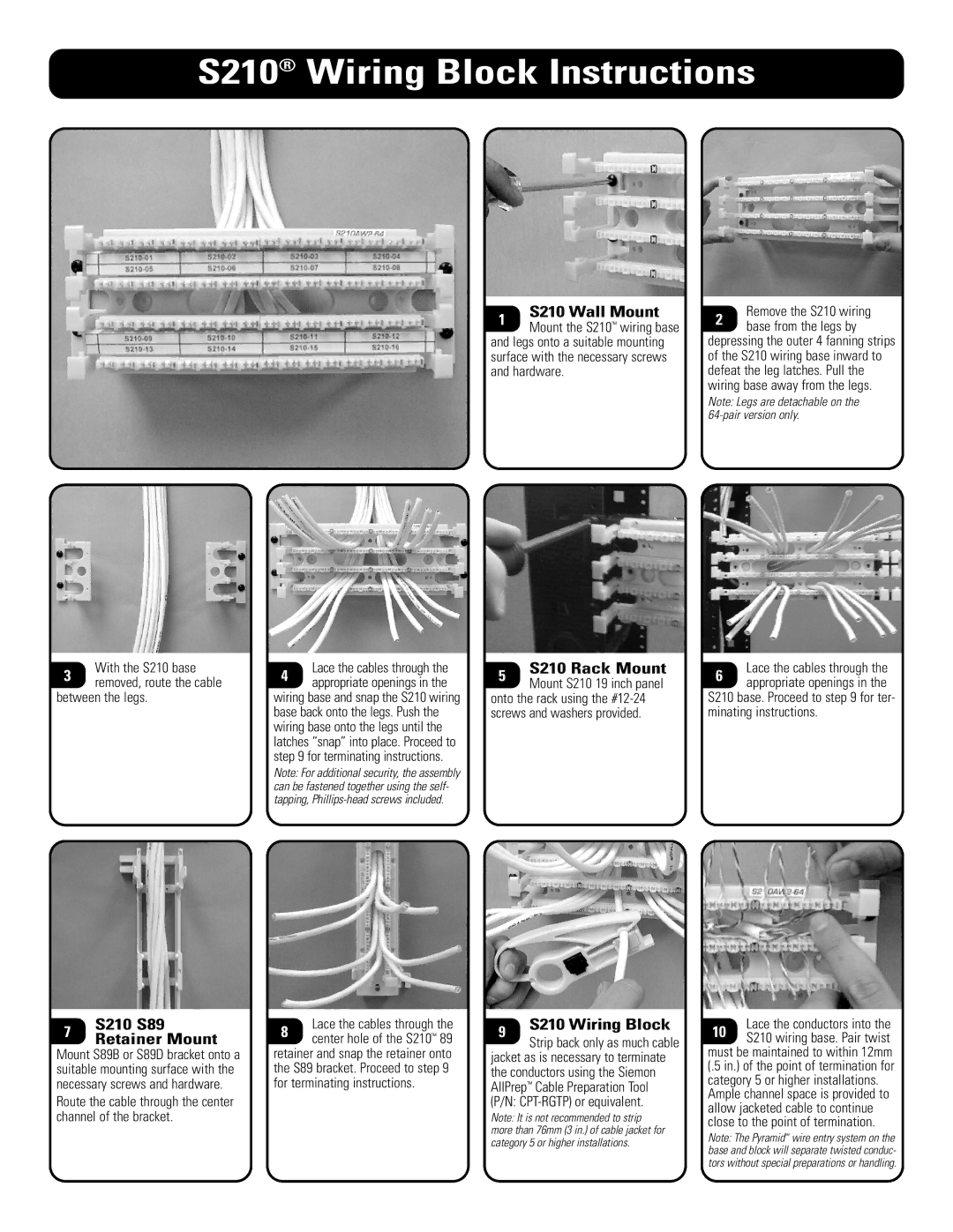
With the S210 base
3 removed, route the cable between the legs.
7 | S210 S89 | |
Retainer Mount | ||
|
Mount S89B or S89D bracket onto a suitable mounting surface with the necessary screws and hardware.
Route the cable through the center channel of the bracket.
Lace the cables through the
4 appropriate openings in the wiring base and snap the S210 wiring base back onto the legs. Push the wiring base onto the legs until the latches “snap” into place. Proceed to step 9 for terminating instructions.
Note: For additional security, the assembly can be fastened together using the self- tapping,
Lace the cables through the
8 center hole of the S210™ 89 retainer and snap the retainer onto the S89 bracket. Proceed to step 9 for terminating instructions.
1S210 Wall Mount
Mount the S210™ wiring base
and legs onto a suitable mounting surface with the necessary screws and hardware.
5S210 Rack Mount
Mount S210 19 inch panel
onto the rack using the
9S210 Wiring Block
Strip back only as much cable
jacket as is necessary to terminate the conductors using the Siemon AllPrep™ Cable Preparation Tool (P/N:
Note: It is not recommended to strip more than 76mm (3 in.) of cable jacket for category 5 or higher installations.
Remove the S210 wiring
2 base from the legs by depressing the outer 4 fanning strips of the S210 wiring base inward to defeat the leg latches. Pull the wiring base away from the legs.
Note: Legs are detachable on the
Lace the cables through the
6 appropriate openings in the
S210 base. Proceed to step 9 for ter- minating instructions.
Lace the conductors into the
10 S210 wiring base. Pair twist must be maintained to within 12mm (.5 in.) of the point of termination for category 5 or higher installations.
Ample channel space is provided to allow jacketed cable to continue close to the point of termination.
Note: The Pyramid™ wire entry system on the base and block will separate twisted conduc- tors without special preparations or handling.