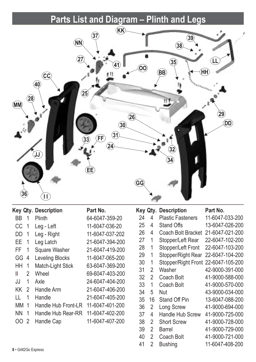
Parts List and Diagram – Plinth and Legs
KK
|
|
|
| 37 |
|
|
| 39 |
|
| |
|
| NN |
|
|
|
|
|
|
| ||
|
|
|
|
|
|
| 38 |
|
| ||
|
|
|
|
|
|
|
|
|
| ||
|
| 27 |
|
| 41 |
|
| 35 |
| LL | |
|
|
|
|
|
|
|
| ||||
|
|
|
|
| OO |
|
|
|
| ||
|
|
|
|
|
|
| BB | HH | |||
|
| CC |
|
|
|
|
| ||||
|
|
|
|
|
|
|
|
|
| ||
|
| 40 |
|
|
|
|
|
|
|
| |
| 28 | 25 |
|
|
|
|
|
|
| ||
|
|
|
|
|
|
|
|
|
| ||
MM |
|
|
|
|
|
|
|
|
|
| |
|
|
|
|
|
| 26 |
|
|
| 29 | |
|
|
|
|
|
|
|
|
|
| ||
|
|
|
|
| 30 |
|
|
|
| DD | |
|
|
|
|
|
|
|
|
|
| ||
|
|
| 33 | FF | 31 |
|
|
|
|
| |
|
|
|
|
|
|
|
|
| |||
|
|
|
|
| 24 |
|
| 32 |
|
| |
|
| JJ |
|
|
|
|
|
|
| ||
|
|
|
|
|
|
| 34 |
|
| ||
|
|
|
|
|
|
|
|
|
| ||
|
|
| EE |
|
|
|
|
|
| ||
|
|
|
|
|
| GG |
|
|
|
| |
36 | I I |
|
|
|
|
|
|
|
| ||
|
|
|
|
|
|
|
|
|
| ||
Key Qty. Description | Part No. |
| Key Qty. Description |
| Part No. | ||||||
BB | 1 | Plinth | 24 | 4 | Plastic Fasteners |
| |||||
CC | 1 | Leg - Left | 25 | 4 | Stand Offs |
| |||||
DD | 1 | Leg - Right | 26 | 4 | Coach Bolt Bracket | ||||||
|
|
|
|
| |||||||
EE | 1 | Leg Latch | 27 | 1 | Stopper/Left Rear |
| |||||
28 | 1 | Stopper/Left Front |
| ||||||||
FF | 1 | Square Washer |
| ||||||||
29 | 1 | Stopper/Right Rear | |||||||||
GG | 4 | Leveling Blocks | |||||||||
30 | 1 | Stopper/Right Front | |||||||||
HH | 1 | ||||||||||
31 | 2 | Washer |
| ||||||||
II | 2 | Wheel |
| ||||||||
32 | 2 | Coach Bolt |
| ||||||||
JJ | 1 | Axle |
| ||||||||
33 | 1 | Coach Bolt |
| ||||||||
KK | 2 | Handle Arm |
| ||||||||
34 | 5 | Nut |
| ||||||||
LL | 1 | Handle |
| ||||||||
35 | 16 | Stand Off Pin |
| ||||||||
|
|
|
|
|
|
| |||||
MM | 1 | Handle Hub | 36 | 2 | Long Screw |
| |||||
|
|
|
|
|
|
| |||||
NN | 1 | Handle Hub | 37 | 4 | Handle Hub Screw |
| |||||
OO | 2 | Handle Cap | 38 | 2 | Short Screw |
| |||||
|
|
|
|
|
| 39 | 2 | Barrel |
| ||
|
|
|
|
|
| 40 | 2 | Coach Bolt |
| ||
|
|
|
|
|
| 41 | 2 | Bushing |
| ||
8 • Grill2Go Express
