APT-641 Speed dome controller
SPECIFICATION
Video Input | 8 CAMERA INPUT and EACH THROUGHOUT |
Video Output | MAIN OUTPUT/SPOT OUTPUT |
LCD Display | 16 x 2 Display |
Alarm Input | up to 8 Inputs |
Preset | 64 Preset Points |
OSD Display | MENU and CAMERA ID (up to 10 characters) |
Function Key | AUTO/AUTO PAN/SWITCHER |
Focus | NEAR/FAR |
Joystick | PAN/TILT/ZOOM Simultaneous Control |
External Units/PC | |
Power Source | DC 12V (500mA) |
Power Consumption | 6W |
Weight | 2kg |
Dimensions | 345(W)x67(H)x206(D)mm |
* Specifications and design subject to change without notice for improvements.
TOKINA Co.,Ltd.
Security Products Division
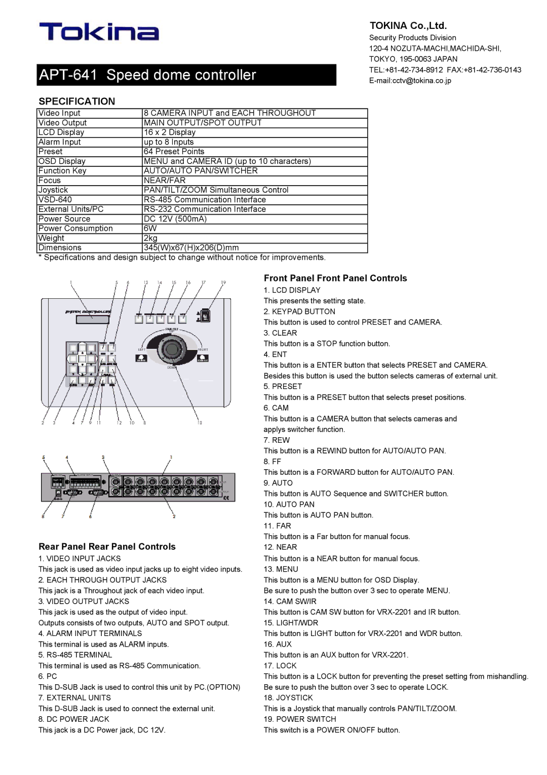
Front Panel Front Panel Controls
| 1. LCD DISPLAY |
| This presents the setting state. |
| 2. KEYPAD BUTTON |
| This button is used to control PRESET and CAMERA. |
| 3. CLEAR |
| This button is a STOP function button. |
| 4. ENT |
| This button is a ENTER button that selects PRESET and CAMERA. |
| Besides this button is used the button selects cameras of external unit. |
| 5. PRESET |
| This button is a PRESET button that selects preset positions. |
| 6. CAM |
| This button is a CAMERA button that selects cameras and |
| applys switcher function. |
| 7. REW |
| This button is a REWIND button for AUTO/AUTO PAN. |
| 8. FF |
| This button is a FORWARD button for AUTO/AUTO PAN. |
| 9. AUTO |
| This button is AUTO Sequence and SWITCHER button. |
| 10. AUTO PAN |
| This button is AUTO PAN button. |
| 11. FAR |
Rear Panel Rear Panel Controls | This button is a Far button for manual focus. |
12. NEAR | |
1. VIDEO INPUT JACKS | This button is a NEAR button for manual focus. |
This jack is used as video input jacks up to eight video inputs. | 13. MENU |
2. EACH THROUGH OUTPUT JACKS | This button is a MENU button for OSD Display. |
This jack is a Throughout jack of each video input. | Be sure to push the button over 3 sec to operate MENU. |
3. VIDEO OUTPUT JACKS | 14. CAM SW/IR |
This jack is used as the output of video input. | This button is CAM SW button for |
Outputs consists of two outputs, AUTO and SPOT output. | 15. LIGHT/WDR |
4. ALARM INPUT TERMINALS | This button is LIGHT button for |
This terminal is used as ALARM inputs. | 16. AUX |
5. | This button is an AUX button for |
This terminal is used as | 17. LOCK |
6. PC | This button is a LOCK button for preventing the preset setting from mishandling. |
This | Be sure to push the button over 3 sec to operate LOCK. |
7. EXTERNAL UNITS | 18. JOYSTICK |
This | This is a Joystick that manually controls PAN/TILT/ZOOM. |
8. DC POWER JACK | 19. POWER SWITCH |
This jack is a DC Power jack, DC 12V. | This switch is a POWER ON/OFF button. |