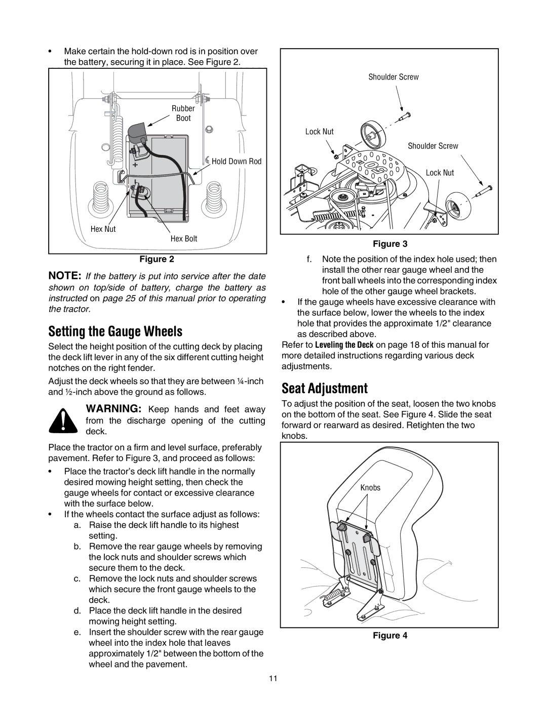
•Make certain the
Rubber |
Boot |
Hold Down Rod |
Hex Nut |
Hex Bolt |
Figure 2
NOTE: If the battery is put into service after the date shown on top/side of battery, charge the battery as instructed on page 25 of this manual prior to operating the tractor.
Setting the Gauge Wheels
Select the height position of the cutting deck by placing the deck lift lever in any of the six different cutting height notches on the right fender.
Adjust the deck wheels so that they are between
WARNING: Keep hands and feet away from the discharge opening of the cutting deck.
Place the tractor on a firm and level surface, preferably pavement. Refer to Figure 3, and proceed as follows:
•Place the tractor’s deck lift handle in the normally desired mowing height setting, then check the gauge wheels for contact or excessive clearance with the surface below.
•If the wheels contact the surface adjust as follows:
a.Raise the deck lift handle to its highest setting.
b.Remove the rear gauge wheels by removing the lock nuts and shoulder screws which secure them to the deck.
c.Remove the lock nuts and shoulder screws which secure the front gauge wheels to the deck.
d.Place the deck lift handle in the desired mowing height setting.
e.Insert the shoulder screw with the rear gauge wheel into the index hole that leaves approximately 1/2" between the bottom of the wheel and the pavement.
Shoulder Screw |
Lock Nut |
Shoulder Screw |
Lock Nut |
Figure 3
f.Note the position of the index hole used; then install the other rear gauge wheel and the front ball wheels into the corresponding index hole of the other gauge wheel brackets.
•If the gauge wheels have excessive clearance with the surface below, lower the wheels to the index hole that provides the approximate 1/2" clearance as described above.
Refer to Leveling the Deck on page 18 of this manual for more detailed instructions regarding various deck adjustments.
Seat Adjustment
To adjust the position of the seat, loosen the two knobs on the bottom of the seat. See Figure 4. Slide the seat forward or rearward as desired. Retighten the two knobs.
Knobs |
Figure 4
11