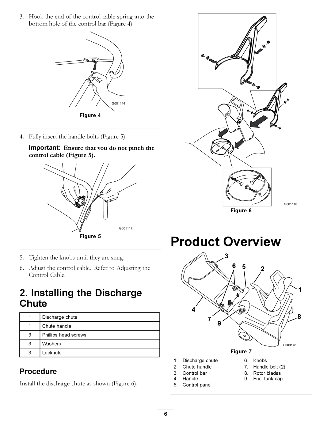
3. Hook the end of the control cable spring into the bottom hole of the control bar (Figure 4).
Figure 4
4. Fully insert the handle bolts (Figure 5).
Important: Ensure that you do not pinch the control cable (Figure 5).
Figure 6
Figure 5
5.Tighten the knobs until they are snug.
6.Adjust the control cable. Refer to Adjusting the Control Cable.
2.Installing the Discharge Chute
1Discharge chute
1Chute handle
3Phillips head screws
3Washers
3Locknuts
Procedure
Install the discharge chute as shown (Figure 6).
Product Overview
|
| Figure 7 |
|
1. | Discharge chute | 6. | Knobs |
2. | Chute handle | 7. | Handle bolt (2) |
3. | Control bar | 8. | Rotor blades |
4. | Handle | 9. | Fuel tank cap |
5. | Control panel |
|
|
|
|
|
|
6
