Jar Top
Specifications
• Body Style:
• AVB, 3/4" Female NPT (53763)
• AVB, 1" Female NPT (53764)
• Flow range (3/4"):
• Flow range (1"):
• Operating pressure:
• Solenoid: 24 V a.c., 60Hz (nominal)
19 V a.c., 60Hz (minimum)
Inrush: 0.40 amps, 11.50 VA @ 24 V a.c.
Holding: 0.20 amps, 5.75 VA @ 24 V a.c.
• Friction Loss: |
|
|
|
|
|
|
|
|
|
|
|
| ||
|
| GPM Flow |
| 0.25 |
| 5 |
| 10 |
| 15 |
| 20 |
| 30 |
|
|
|
|
|
|
|
| |||||||
|
| PSI Loss (3/4") |
| 2.0 |
| 4.2 |
| 4.2 |
| 4.8 |
| 7.6 |
| – |
|
|
|
|
|
|
|
|
|
|
|
|
|
| |
(1") |
| 2.0 |
| 2.1 |
| 3.1 |
| 2.3 |
| 3.8 |
| 8.1 | ||
Valve Installation Guidelines
Ensure the following requirements, in addition to all local code requirements, are met when installing the Toro Jar Top
•The installed height, measured from the valve base, must not be less than of 6" above the highest downstream outlet controlled by the valve.
•The
•The
•The installation site must be accessible to allow inspection and servicing.
•Additional control valves must not be installed downstream of the anti- siphon valve.
•The
•The valve must not be operated continuously for more than 12 hours in any
•Installing a manual
•Where local water pressure exceeds 70 psi, a pressure regulator should be used. (See Uniform Plumbing Code, Sec. 1007 [b].) It is advisable to use a regulator with any automatic valve to assure long life as well as uniform and controllable operation.
Installation Procedure
1.From the
2.Flush the supply line thoroughly to remove all traces of dirt and debris.
3.Prepare two 1" slip/male thread adapters with three to five complete wraps of PTFE tape, evenly covering the threads.
![]() CAUTION: Use only PTFE tape on threaded valve connections. Pipe dope will damage plastic threads.
CAUTION: Use only PTFE tape on threaded valve connections. Pipe dope will damage plastic threads.
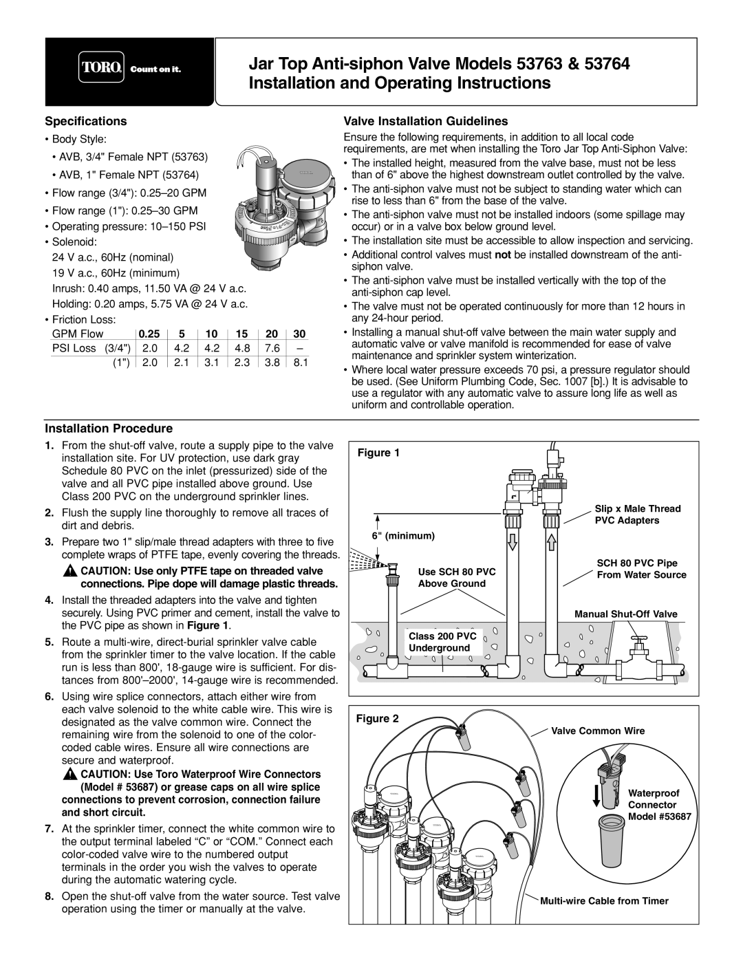
4.Install the threaded adapters into the valve and tighten securely. Using PVC primer and cement, install the valve to the PVC pipe as shown in Figure 1.
5.Route a
6.Using wire splice connectors, attach either wire from each valve solenoid to the white cable wire. This wire is designated as the valve common wire. Connect the remaining wire from the solenoid to one of the color- coded cable wires. Ensure all wire connections are
secure and waterproof.
![]() CAUTION: Use Toro Waterproof Wire Connectors (Model # 53687) or grease caps on all wire splice connections to prevent corrosion, connection failure
CAUTION: Use Toro Waterproof Wire Connectors (Model # 53687) or grease caps on all wire splice connections to prevent corrosion, connection failure
and short circuit.
7.At the sprinkler timer, connect the white common wire to the output terminal labeled “C” or “COM.” Connect each
8.Open the
Figure 1
Slip x Male Thread
PVC Adapters
6" (minimum) |
|
Use SCH 80 PVC | SCH 80 PVC Pipe |
From Water Source | |
Above Ground |
|
| Manual |
Class 200 PVC |
|
Underground |
|
Figure 2 |
Valve Common Wire |
Waterproof |
Connector |
Model #53687 |