1600 XP UPS specifications
The Toshiba 1600 XP Uninterruptible Power Supply (UPS) is designed to provide robust backup power and exceptional electrical protection for critical equipment in various applications, including data centers, telecommunications, and industrial settings. This model is geared toward ensuring high reliability in power management, safeguarding against power disturbances that could jeopardize operational continuity.One of the significant features of the Toshiba 1600 XP UPS is its high efficiency rating. Operating at up to 94% efficiency, it minimizes energy consumption and reduces overall operating costs. This efficiency also contributes to lower heat generation, which helps maintain optimal operating conditions and prolongs the lifespan of both the UPS and connected equipment.
The 1600 XP utilizes advanced double conversion online technology, which provides clean and stable power by continuously regulating voltage and frequency. This technology keeps connected loads free from surges, sags, and transients, ensuring that sensitive electronics operate without complications even in the event of a power failure.
This UPS model is equipped with a modular design, allowing for easy scalability and maintenance. As power demands grow, users can expand the system seamlessly by adding additional modules. Furthermore, the modular architecture simplifies maintenance, as components can be replaced without needing to power down the entire system.
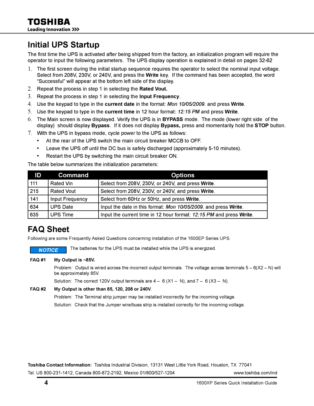
The Toshiba 1600 XP also includes user-friendly features such as an intuitive LCD display, which provides real-time information on UPS status, power consumption, and battery health. Alarm notifications and event logging capabilities further enhance monitoring and management, enabling proactive maintenance and swift response to any issues.
Another characteristic of the Toshiba 1600 XP is its extensive battery management system. This feature extends battery life through smart charging cycles and temperature compensation, ensuring reliable backup power when it's most needed. Additionally, the UPS can be integrated with advanced communication protocols, allowing seamless interaction with building management systems for centralized monitoring.
In summary, the Toshiba 1600 XP UPS is a reliable and efficient power protection solution that combines advanced technology with user-friendly features, making it an ideal choice for industries needing uninterrupted power supply. With its modular design, high efficiency, and robust protection capabilities, it stands out as a valuable asset for maintaining operational integrity in today’s power-sensitive environments.

