FIELD REPLACEABLE UNIT DOCUMENTATION
TM
Satellite
1900 Series
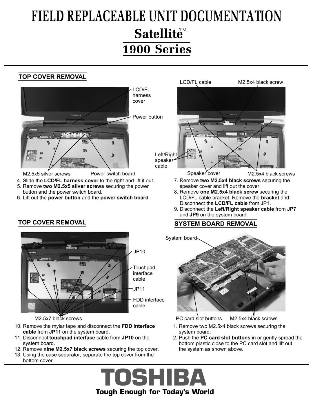
TOP COVER REMOVAL
LCD/FL cable | M2.5x4 black screw |
LCD/FL harness cover
Power button
Left/Right speaker cable
|
| M2.5x5 silver screws | Power switch board |
|
|
| Speaker cover | M2.5x4 black screws | ||
4. | Slide the LCD/FL harness cover to the right and lift it out. | 7. | Remove two M2.5x4 black screws securing the | |||||||
5. | Remove two M2.5x5 silver screws securing the power |
|
|
| speaker cover and lift out the cover. | |||||
|
| button and the power switch board. | 8. | Remove one M2.5x4 black screw securing the | ||||||
6. | Lift out the power button and the power switch board. |
|
|
| LCD/FL cable bracket. Remove the bracket and | |||||
|
|
|
|
|
|
| Disconnect the LCD/FL cable from JP1. | |||
|
|
|
| 9. | Disconnect the Left/Right speaker cable from JP7 | |||||
|
|
|
|
|
|
| and JP9 on the system board. | |||
| TOP COVER REMOVAL |
|
|
|
| |||||
|
|
|
| SYSTEM BOARD REMOVAL |
|
| ||||
|
|
|
|
|
|
|
|
|
|
|
System board
JP10
Touchpad interface cable
![]() JP11
JP11
![]() FDD interface cable
FDD interface cable
M2.5x7 black screws | PC card slot buttons M2.5x4 black screws |
10.Remove the mylar tape and disconnect the FDD interface cable from JP11 on the system board.
11.Disconnect touchpad interface cable from JP10 on the system board.
12.Remove nine M2.5x7 black screws securing the top cover.
13.Using the case separator, separate the top cover from the bottom cover
1.Remove two M2.5x4 black screws securing the system board.
2.Push the PC card slot buttons in or gently spread the bottom plastic close to the PC card slot and lift out the system as shown above.
TOSHIBA
Tough Enough for Today’s World