42HL167 47HL167 52HL167
Safety Precautions
Dear Customer
Additional Safety Precautions
Important Safety Instructions
Installation, Care, and Service
Installation
Service
Care
To Display your LCD TV on the included Pedestal Stand
To Display your LCD TV using a Wall Bracket
Choosing a location for your LCD TV
Removing the Pedestal Stand
Important notes about your LCD TV
Part
Trademark Information
Contents
Troubleshooting
Introduction
Features of your new TV
Welcome to Toshiba
Introduction
Green and Yellow LEDs
TV front and side panel controls and connections
HD1, ColorStream HD2, Hdmi 1, Hdmi 2, Hdmi 3, PC
TV back panel connections
ColorStream HD-1 and ColorStream HD-2
Overview of cable types
Connecting your TV
About the connection illustrations
You will need
Connecting a VCR and antenna or Cable TV no Cable box
To view the antenna or Cable signal
To view the VCR
Coaxial cables Video cable
Connecting a VCR with S-video and a cable box
To view basic and premium Cable channels
Standard audio cables
To view the VCR or view and record antenna channels
To view antenna or Cable channels
To view the DVD player
To record a TV program while watching a DVD
To control the devices
To connect the IR blaster cable
If you cannot locate the device’s infrared sensor
To view the camcorder video
Connecting a camcorder
Select the Video 2 video input source on the TV
To view the Hdmi device video
Connecting an Hdmi or DVI device to the Hdmi input
To connect an Hdmi device, you will need
To connect a DVI device, you will need
Before controlling the devices
CE-Link connection
Three Hdmi cables
Connecting an audio system
To control the audio
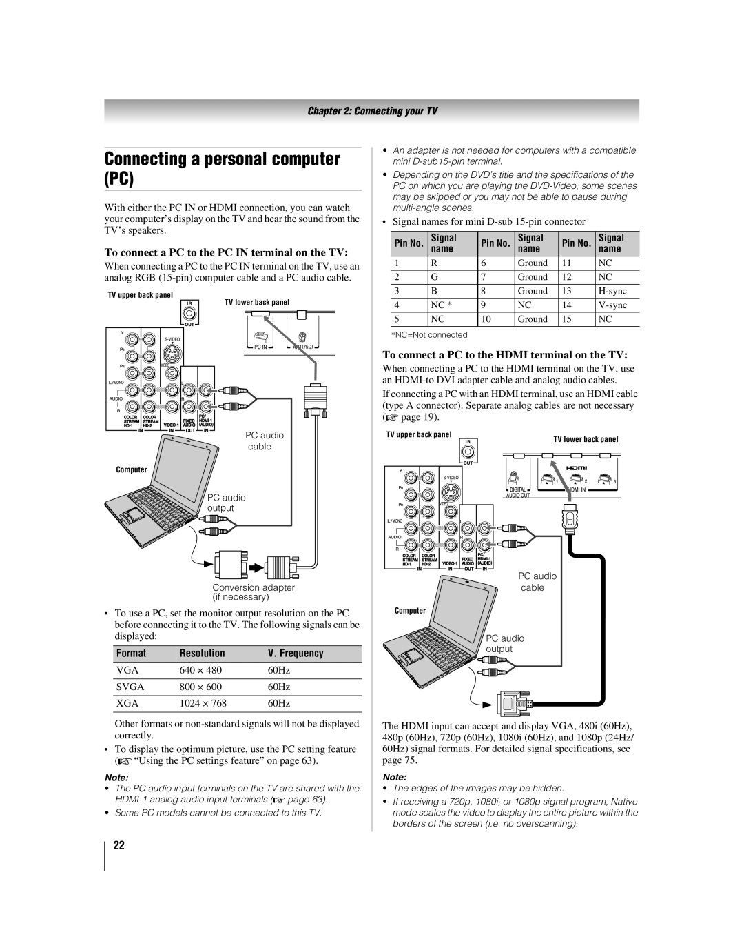
To connect a PC to the PC in terminal on the TV
Connecting a personal computer PC
To connect a PC to the Hdmi terminal on the TV
Remote control effective range
Using the remote control
Installing the remote control batteries
To install the remote control batteries
Learning about the remote control
TheaterWide 1/2/3, Full, 43 HD, and Native
Combo Receiver
Remote Control functional key chart
Satellite DVD
CH RTN
Mode Select Default device mode control before programming
Using the remote control to operate your other devices
Device code setup
Mode Select Device mode control after programming
To unlock the remote control’s volume keys
Using the volume lock feature
Operational feature reset
To reset the remote control
Cable boxes
TVs
Satellite receivers
DVDs
3D LAB
DVD/VCR Combo
VCRs
KEC
STS
DBS/PVR Combo
PVRs
Cable/PVR Combo
Audio Amp
Audio Amp/Tuners
SAE
Main menu layout
Menu layout and navigation
Icon Option
Installation
Setup/Installation menu layout
Setup menu
Thinc menu
Navigating the menu system
Video
To configure the ANT input source
Setting up your TV
Configuring the antenna input source for the ANT terminal
Selecting the menu language
To program channels automatically
Programming channels automatically
Manually adding and deleting channels in the channel memory
To add or delete channels in the channel memory
Setting the Auto Input feature
To turn off the Auto Input
To reset Auto Input
Labeling channels
To assign channel labels
To remove channel labels
Setting the Hdmi audio mode
To set the Hdmi audio mode
To delete the custom label
Reset Factory Defaults
Viewing the digital signal meter
Viewing the system status
To set the Power-On Mode feature
Selecting the Power-On Mode
To cancel the reset
Highlight No and press T
To label the video input sources
Using the TV’s features
Labeling the video input sources
Press CABLE/SAT, DVD, or VCR/PVR
Tuning channels using Channel Browser
Tuning channels
Favorites Browser
Elements of the Channel Browser
Adding and clearing channels and inputs in the History List
Switching between two channels using Channel Return
Tuning to a specific channel programmed or unprogrammed
Switching between two channels using SurfLock
TheaterWide 1 picture size for 43 format programs
Selecting the picture size
Natural picture size
TheaterWide 2 picture size for letter box programs
To set the scroll settings
Full picture size for 169 480i, 480p source programs only
Using the Freeze feature
Selecting the picture mode
Adjusting the picture
Adjusting the picture quality
Base closed captions
Using the closed caption mode
Digital CC Settings
To view captions or text
Using the digital audio selector
Adjusting the audio
Using the Closed Caption button on the remote control
CC Selector
To listen to stereo sound
Press C or c to adjust the level
Selecting stereo/SAP broadcasts
MTS field, select Stereo
Using the StableSound feature
Using the Dolby Digital Dynamic Range Control feature
If you cannot remember your PIN code
Using the Locks menu
Entering the PIN code
Changing your PIN code
To block and unblock TV programs and movies
Press b to highlight Enable Rating Blocking
Blocking TV programs and movies by rating V-Chip
To download the additional rating system if available
To block channels
Blocking channels
To unblock individual channels
Using the input lock feature
Unlocking programs temporarily
Using the GameTimer
Using the control panel lock feature
To adjust the PC settings
Using the PC settings feature
Setting the PC Audio
To set the PC Audio
Using CE-Link
Setting the sleep timer
CE-Link playback device HD DVD player, etc. control
To set the CE-Link Setup
Volume and Mute controls of Audio Receiver
Other CE-Link functions
Understanding the last mode memory feature
Understanding the auto power off feature
Displaying TV status information
Using dynamic contrast
Using the TV’s advanced features
Using the advanced picture settings features
Using the static gamma feature
To select the color temperature
Selecting the color temperature
Using CableClear digital noise reduction
To change the CableClear settings
Using the ColorMaster feature
Using Mpeg noise reduction
Using Color Palette Adjustment
To turn on Game Mode
Using the Game Mode feature
To reset ColorMaster to its factory settings
To turn off Game Mode
To adjust the WOW settings
Using the advanced audio settings features
Using the SRS WOW surround sound feature
Highlight Advanced Audio Settings and press T
Troubleshooting
General troubleshooting
Rating blocking V-Chip problems
Channel tuning problems
Closed caption problems
No CE-Link operation
LED Indication Condition Solution
LED indications
Format Resolution Frequency Pixel Clock Frequency
Specifications
Appendix
Limited United States Warranty
For LCD Televisions 26 and Larger
Limited Canadian Warranty
For Toshiba Brand Flat Panel Televisions
Disclaimer and Limitation of Remedy
Appendix
Index
Freeze
Page
07-05