PIN ASSIGNMENT
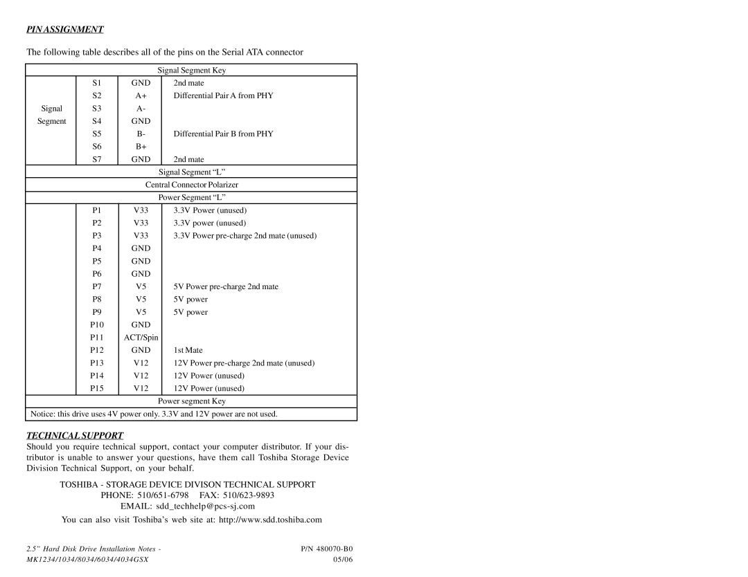
The following table describes all of the pins on the Serial ATA connector
|
|
|
| Signal Segment Key |
| |
|
| S1 | GND |
| 2nd mate |
|
|
| S2 | A+ |
| Differential Pair A from PHY |
|
| Signal | S3 | A- |
|
|
|
| Segment | S4 | GND |
|
|
|
|
| S5 | B- |
| Differential Pair B from PHY |
|
|
| S6 | B+ |
|
|
|
|
| S7 | GND |
| 2nd mate |
|
|
|
|
| Signal Segment “L” |
| |
|
|
| Central Connector Polarizer |
| ||
|
|
|
|
|
|
|
|
|
|
| Power Segment “L” |
| |
|
|
|
|
|
|
|
|
| P1 | V33 |
| 3.3V Power (unused) |
|
|
| P2 | V33 |
| 3.3V power (unused) |
|
|
| P3 | V33 |
| 3.3V Power |
|
|
| P4 | GND |
|
|
|
|
| P5 | GND |
|
|
|
|
| P6 | GND |
|
|
|
|
| P7 | V5 |
| 5V Power |
|
|
| P8 | V5 |
| 5V power |
|
|
| P9 | V5 |
| 5V power |
|
|
| P10 | GND |
|
|
|
|
| P11 | ACT/Spin |
|
| |
|
| P12 | GND |
| 1st Mate |
|
|
| P13 | V12 |
| 12V Power |
|
|
| P14 | V12 |
| 12V Power (unused) |
|
|
| P15 | V12 |
| 12V Power (unused) |
|
|
|
|
|
|
|
|
|
|
|
| Power segment Key |
| |
Notice: this drive uses 4V power only. 3.3V and 12V power are not used.
TECHNICAL SUPPORT
Should you require technical support, contact your computer distributor. If your dis- tributor is unable to answer your questions, have them call Toshiba Storage Device Division Technical Support, on your behalf.
TOSHIBA - STORAGE DEVICE DIVISON TECHNICAL SUPPORT
PHONE:
EMAIL:
You can also visit Toshiba’s web site at: http://www.sdd.toshiba.com
2.5” Hard Disk Drive Installation Notes - | P/N |
MK1234/1034/8034/6034/4034GSX | 05/06 |