RBC-FDP2-F-PE Interface
Installation and Operating Instructions
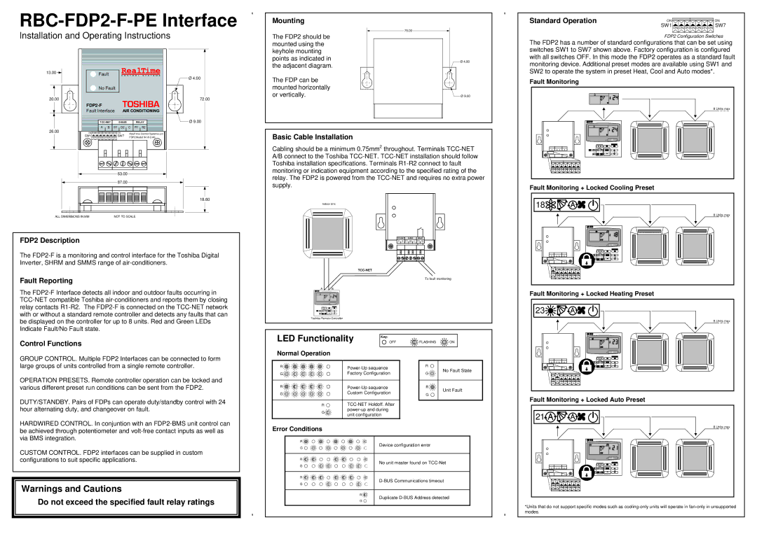
Mounting
The FDP2 should be mounted using the keyhole mounting points as indicated in the adjacent diagram.
75.00
Ø 4.00 |
Standard Operation | ON | ON |
| SW1 | SW7 |
| FDP2 Configuration Switches | |
The FDP2 has a number of standard configurations that can be set using switches SW1 to SW7 shown above. Factory configuration is configured with all switches OFF. In this mode the FDP2 operates as a standard fault monitoring device. Additional preset modes are available using SW1 and
13.00 ![]()
20.00
26.00
![]() Fault
Fault
![]() No Fault
No Fault
Fault Interface
| RELAY |
|
A B D1 D2 C R1 R2
ON | ON | RealTime Control Systems Ltd |
Ø 4.00
72.00
![]() Ø 9.00
Ø 9.00
The FDP can be mounted horizontally or vertically.
Ø 9.00 |
SW2 to operate the system in preset Heat, Cool and Auto modes*.
Fault Monitoring
8 Units max
SW1 | SW7 | FDP2 Model |
Basic Cable Installation
Cabling should be a minimum 0.75mm2 throughout. Terminals
| 63.00 |
| 87.00 |
| 18.60 |
ALL DIMENSIONS IN MM | NOT TO SCALE |
FDP2 Description
The
Fault Reporting
The
Control Functions
relay. The FDP2 is powered from the
Indoor Unit
|
|
|
|
|
|
|
|
|
|
| RELAY |
| |||||
| A B | D1 D2 C | R1 R2 |
| ||||
|
|
|
|
|
|
|
|
|
|
|
|
|
|
|
|
|
|
|
|
|
|
|
|
|
|
|
|
|
|
|
|
|
|
|
|
|
|
|
|
|
|
|
|
|
To fault monitoring
A | B |
Toshiba Remote Controller
LED Functionality | OFF | FLASHING | ON |
| Key: |
|
|
Normal Operation |
|
|
|
Fault Monitoring + Locked Cooling Preset
18![]()
![]()
![]()
![]()
![]()
![]()
![]()
![]()
![]()


8 Units max
Fault Monitoring + Locked Heating Preset
23![]()
![]()
![]()
![]()
![]()
![]()
![]()
![]()
![]()
![]()


8 Units max
GROUP CONTROL. Multiple FDP2 Interfaces can be connected to form large groups of units controlled from a single remote controller.
OPERATION PRESETS. Remote controller operation can be locked and various different preset run conditions can be sent from the FDP2.
DUTY/STANDBY. Pairs of FDPs can operate duty/standby control with 24 hour alternating duty, and changeover on fault.
R ![]()
![]()
![]()
![]()
![]() G
G![]()
![]()
![]()
![]()
![]()
R ![]()
![]()
![]()
![]()
G![]()
![]()
![]()
![]()
R ![]()
G![]()
Power-Up sequence Factory Configuration
R![]()
G![]()
R ![]() G
G ![]()
No Fault State
Unit Fault
Fault Monitoring + Locked Auto Preset
21![]()
![]()
![]()
![]()
![]()
![]()
![]()
![]()
HARDWIRED CONTROL. In conjuntion with an
Error Conditions
8 Units max
CUSTOM CONTROL. FDP2 interfaces can be supplied in custom configurations to suit specific applications.
Warnings and Cautions
Do not exceed the specified fault relay ratings
R ![]()
G ![]()
R ![]()
![]()
![]()
![]()
![]()
![]()
![]()
![]()
![]()
![]()
![]()
![]() G
G ![]()
![]()
![]()
![]()
![]()
![]()
![]()
![]()
![]()
R ![]()
![]()
![]()
![]()
![]()
![]()
![]() G
G ![]()
![]()
![]()
![]()
![]()
![]()
![]()
R ![]()
G ![]()
Device configuration error
No unit master found on
Duplicate
*Units that do not support specific modes such as