FDP2 Advanced Operation |
|
| FDP2 Group Control | FDP2 Duty/Standby Operation |
| ||
ADDRESSING |
|
|
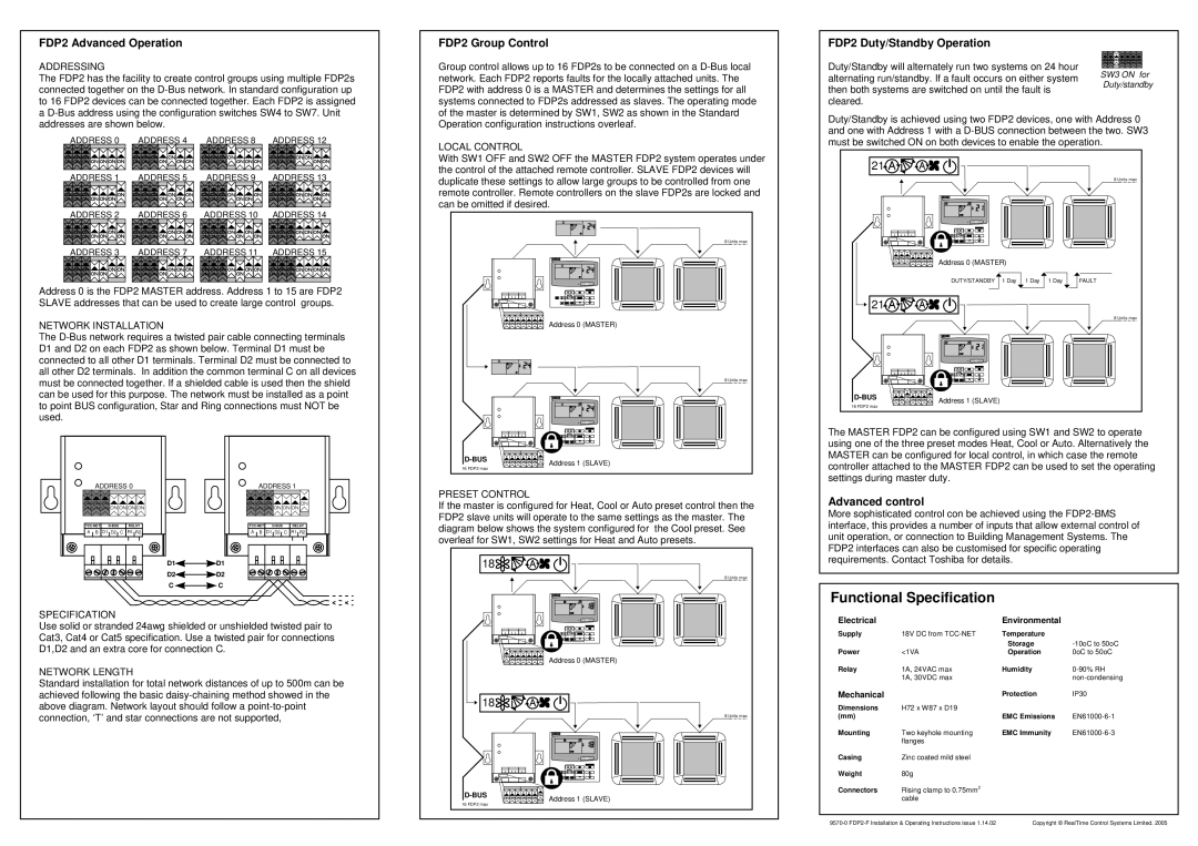
| Group control allows up to 16 FDP2s to be connected on a | Duty/Standby will alternately run two systems on 24 hour | SW3 ON for | |
The FDP2 has the facility to create control groups using multiple FDP2s | network. Each FDP2 reports faults for the locally attached units. The | alternating run/standby. If a fault occurs on either system | |||||
Duty/standby | |||||||
connected together on the | FDP2 with address 0 is a MASTER and determines the settings for all | then both systems are switched on until the fault is | |||||
| |||||||
to 16 FDP2 devices can be connected together. Each FDP2 is assigned | systems connected to FDP2s addressed as slaves. The operating mode | cleared. |
| ||||
a | of the master is determined by SW1, SW2 as shown in the Standard | Duty/Standby is achieved using two FDP2 devices, one with Address 0 | |||||
addresses are shown below. |
|
| Operation configuration instructions overleaf. | ||||
|
| and one with Address 1 with a | |||||
ADDRESS 0 | ADDRESS 4 | ADDRESS 8 | ADDRESS 12 |
| |||
LOCAL CONTROL | must be switched ON on both devices to enable the operation. | ||||||
|
|
|
|
|
| ||
|
|
|
| With SW1 OFF and SW2 OFF the MASTER FDP2 system operates under | 21 |
| |
|
|
|
| the control of the attached remote controller. SLAVE FDP2 devices will |
| ||
ADDRESS 1 | ADDRESS 5 | ADDRESS 9 | ADDRESS 13 |
|
| ||
duplicate these settings to allow large groups to be controlled from one |
| 8 Units max | |||||
|
|
|
|
|
| ||
|
|
|
| remote controller. Remote controllers on the slave FDP2s are locked and |
|
| |
|
|
|
| can be omitted if desired. |
|
| |
ADDRESS 2 | ADDRESS 6 | ADDRESS 10 | ADDRESS 14 |
|
|
| |
8 Units max |
ADDRESS 3 ADDRESS 7 ADDRESS 11 ADDRESS 15 |
|
| Address 0 (MASTER) |
| DUTY/STANDBY 1 Day 1 Day 1 Day FAULT |
Address 0 is the FDP2 MASTER address. Address 1 to 15 are FDP2 |
|
SLAVE addresses that can be used to create large control groups. | 21 |
8 Units max
NETWORK INSTALLATION | Address 0 (MASTER) |
| |
The |
|
| |
D1 and D2 on each FDP2 as shown below. Terminal D1 must be |
|
| |
connected to all other D1 terminals. Terminal D2 must be connected to |
|
| |
all other D2 terminals. In addition the common terminal C on all devices |
|
| |
must be connected together. If a shielded cable is used then the shield | 8 Units max |
| |
|
| ||
can be used for this purpose. The network must be installed as a point | Address 1 (SLAVE) | ||
to point BUS configuration, Star and Ring connections must NOT be | 16 FDP2 max | ||
| |||
used. |
|
|
|
|
|
|
|
|
|
|
| The MASTER FDP2 can be configured using SW1 and SW2 to operate | |||
|
|
|
|
|
|
|
|
| using one of the three preset modes Heat, Cool or Auto. Alternatively the | |||
|
|
|
|
|
| Address 1 (SLAVE) |
| MASTER can be configured for local control, in which case the remote | ||||
|
|
|
|
|
|
| controller attached to the MASTER FDP2 can be used to set the operating | |||||
|
|
|
|
|
| 16 FDP2 max |
| |||||
|
|
|
|
|
|
|
| |||||
ADDRESS 0 | ADDRESS 1 |
|
|
| settings during master duty. |
|
| |||||
PRESET CONTROL |
|
|
|
|
|
| ||||||
|
|
|
|
|
|
|
| Advanced control |
|
| ||
|
|
|
|
|
| If the master is configured for Heat, Cool or Auto preset control then the |
|
| ||||
|
|
|
|
|
| More sophisticated control con be achieved using the | ||||||
|
|
|
|
|
| FDP2 slave units will operate to the same settings as the master. The | ||||||
|
|
|
|
|
| interface, this provides a number of inputs that allow external control of | ||||||
RELAY | RELAY | diagram below shows the system configured for | the Cool preset. See | |||||||||
A B | D1 D2 | C R1 R2 | A B | D1 D2 | C R1 R2 | unit operation, or connection to Building Management Systems. The | ||||||
|
|
|
|
|
| overleaf for SW1, SW2 settings for Heat and Auto presets. | ||||||
|
|
|
|
|
| FDP2 interfaces can also be customised for specific operating | ||||||
|
|
|
|
|
|
|
|
| ||||
|
| D1 | D1 |
|
| 18 |
|
| requirements. Contact Toshiba for details. |
| ||
|
|
|
|
|
|
|
|
|
| |||
|
| D2 | D2 |
|
|
|
| 8 Units max |
|
|
|
|
|
| C | C |
|
|
|
|
| Functional Specification |
|
| |
|
|
|
|
|
|
|
|
|
|
| ||
SPECIFICATION |
|
|
|
|
|
|
| Electrical |
| Environmental |
| |
Use solid or stranded 24awg shielded or unshielded twisted pair to |
|
|
|
|
| |||||||
|
|
| Supply | 18V DC from | Temperature |
| ||||||
Cat3, Cat4 or Cat5 specification. Use a twisted pair for connections |
|
|
|
| ||||||||
|
|
|
|
| Storage | |||||||
D1,D2 and an extra core for connection C. |
|
|
|
|
|
|
| |||||
|
|
|
|
| Power | <1VA | Operation | 0oC to 50oC | ||||
|
|
|
|
|
|
| Address 0 (MASTER) |
|
|
|
|
|
NETWORK LENGTH |
|
|
|
|
|
| Relay | 1A, 24VAC max | Humidity | |||
Standard installation for total network distances of up to 500m can be |
|
|
|
| 1A, 30VDC max |
| ||||||
|
|
|
|
|
|
| ||||||
achieved following the basic | 18 |
|
| Mechanical |
| Protection | IP30 | |||||
above diagram. Network layout should follow a |
|
| Dimensions | H72 x W87 x D19 |
|
| ||||||
|
|
| EMC Emissions | |||||||||
connection, ‘T’ and star connections are not supported, |
|
|
| 8 Units max | (mm) |
| ||||||
|
|
|
|
|
|
|
|
| Mounting | Two keyhole mounting | EMC Immunity | |
|
|
|
|
|
|
|
|
|
| flanges |
|
|
|
|
|
|
|
|
|
|
| Casing | Zinc coated mild steel |
|
|
|
|
|
|
|
|
|
|
| Weight | 80g |
|
|
|
|
|
|
|
|
|
| Connectors | Rising clamp to 0.75mm2 |
|
| |
|
|
|
|
|
| Address 1 (SLAVE) |
|
| cable |
|
| |
|
|
|
|
|
| 16 FDP2 max |
|
|
|
| ||
|
|
|
|
|
|
|
|
|
|
|
| |
Copyright © RealTime Control Systems Limited. 2005 |