Specifications (Continued)
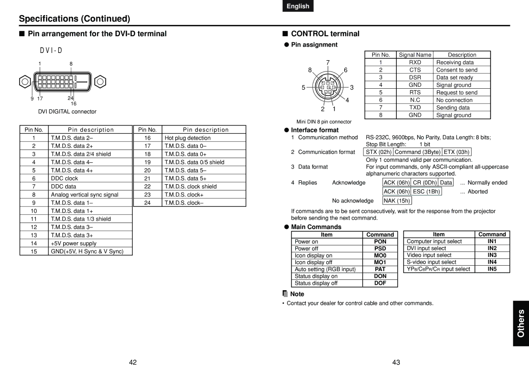
■Pin arrangement for the DVI-D terminal
D V I - D
| 1 |
| 8 | ||||
|
|
|
|
|
|
|
|
|
|
|
|
|
|
|
|
9 17 24
16
English Français Español Deutsch Italiano Português Svenska
■CONTROL terminal
●Pin assignment
|
|
| Pin No. | Signal Name | Description |
| 7 |
| 1 | RXD | Receiving data |
8 | 6 |
| 2 | CTS | Consent to send |
|
|
| 3 | DSR | Data set ready |
5 |
| 3 | 4 | GND | Signal ground |
| 5 | RTS | Request to send | ||
|
|
| |||
| 4 |
| 6 | N.C | No connection |
2 | 1 |
| 7 | TXD | Sending data |
DVI DIGITAL connector
Pin No. | Pin description |
1 | T.M.D.S. data 2– |
2 | T.M.D.S. data 2+ |
3 | T.M.D.S. data 2/4 shield |
4 | T.M.D.S. data 4– |
5 | T.M.D.S. data 4+ |
6 | DDC clock |
7 | DDC data |
8 | Analog vertical sync signal |
9 | T.M.D.S. data 1– |
10 | T.M.D.S. data 1+ |
11 | T.M.D.S. data 1/3 shield |
12 | T.M.D.S. data 3– |
Pin No. | Pin description |
16 | Hot plug detection |
17 | T.M.D.S. data 0– |
18 | T.M.D.S. data 0+ |
19 | T.M.D.S. data 0/5 shield |
20 | T.M.D.S. data 5– |
21 | T.M.D.S. data 5+ |
22 | T.M.D.S. clock shield |
23 | T.M.D.S. clock+ |
24 | T.M.D.S. clock– |
8 | GND | Signal ground |
Mini DIN 8 pin connector
●Interface format
1 | Communication method | ||||||||||||
|
|
|
| Stop Bit Length: | 1 bit |
|
| ||||||
2 | Communication format |
| STX (02h) | Command (3Byte) | ETX (03h) |
| |||||||
|
|
|
| Only 1 command valid per communication. | |||||||||
3 | Data format |
|
| For input commands, only | |||||||||
|
|
|
| alphanumeric characters supported. |
|
| |||||||
|
|
|
|
|
|
|
|
|
| ||||
4 | Replies | Acknowledge |
| ACK (06h) | CR (0Dh) | Data |
| ... Normally ended | |||||
|
|
|
|
|
|
|
|
| |||||
|
|
|
|
| ACK (06h) | ESC (1Bh) |
| ... Aborted | |||||
|
|
|
|
|
|
|
|
|
|
|
|
|
|
|
| No acknowledge | NAK (15h) |
|
|
|
|
|
|
| |||
If commands are to be sent consecutively, wait for the response from the projector before sending the next command.
●Main Commands
13 | T.M.D.S. data 3+ |
14 | +5V power supply |
15 | GND(+5V, H Sync & V Sync) |
Item | Command |
Power on | PON |
Power off | PSD |
Icon display on | MO0 |
Icon display off | MO1 |
Auto setting (RGB input) | PAT |
Status display on | DON |
Status display off | DOF |
Item | Command |
Computer input select | IN1 |
DVI input select | IN2 |
Video input select | IN3 |
IN4 | |
YPB/CBPR/CR input select | IN5 |
![]() Note
Note
• Contact your dealer for control cable and other commands.
Others
42 | 43 |