INSTALLATION INSTRUCTION FOR AUTOMATIC TOILET/URINAL FLUSH VALVE 
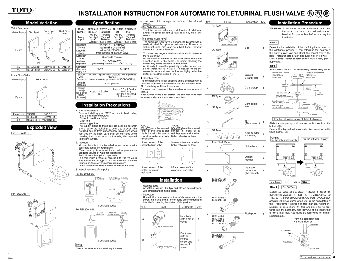
Model Variation
Toilet Flush Valve
| Water Supply Top Spud | Back Spud | Back Spud |
| Floor | Wall |
| |
Figure
AC | TET2ANS-32 TET2ANS-33 TET2ANS-31 |
DC | TET2DNS-32 TET2DNS-33 TET2DNS-31 |
Specification
Model | TET2ANS | | TET2DNS | TEU2ANS | | TEU2DNS |
Number | -32,33,31 | | -32,33,31 | -11,21 | | -11,21 |
| 10V DC | | Alkaline | 10V DC | | Alkaline |
Power | Supplied | | Type AA | Supplied | | Type AA |
supply | by AC | | Batteries | by AC | | Batteries |
| Adapter | | 1.5V x 4pcs. | Adapter | | 1.5V x 4pcs. |
Dimensions | | 12-5/8"(H) x 14-3/16"(W) | |
(cover) | | (320mm(H) x 360mm(W)) |
Detection | | | Within 31-1/2"(800mm) | |
range | from the front of the flush valve |
Detection | | | 6 seconds or more | |
time | | | |
| | | | | |
| | | | |
Ambient | | | 32-104˚F(0-40˚C) | |
temperature | (water temperature: 34-104˚F(1-40˚C)) |
| | | | | | |
Connection | | | | | | |
of the water | 1"NPT | 3/4"NPT |
supply pipe | | | | | | |
4. Use care not to damage the surface of the infrared |
sensor. |
5. For Toilet Flush Valve |
The toilet sensor valve may not function if toilet seat |
and/or lid cover are left upright as it may block the |
sensor. |
6. For Urinal Flush Valve |
The automatic flush valve is designed to be used with a |
washout urinal for optimum performance. However, a |
siphon jet urinal may also be substitutional. Blowout |
urinals are not recommended. |
7. The detection range of the infrared sensor is shown in |
the figure below. |
Do not install a handrail or any other object within the |
detection zone of the sensor, as object blocking the |
sensor may cause the valve to malfunction. |
Additionally, to avoid the possibility of valve malfunction, |
do not install the flush valve in a location where the |
sensor faces a stainless wall, other highly reflective |
Item | Figure | Description Q’ty |
AC Type
Only for toilet flush valve
C | Box | 1 |
| DC Type | |
| Battery case | |
Only for toilet flush valve
Installation Procedure
WARNING: To minimize the risk of electrical shock and fire hazard, be sure to turn off and lock out breaker for power line before starting the installation.
Step 1
Determine the installation of the box fixing frame based on the toilet/urinal position. Then determine the location of the water supply pipe and attach the control stop to the pipe. Thereafter bore a flush pipe guide hole in the wall.
Slide a thread solder adapter on the water supply pipe if applicable.
Note
Attach the control stop before installing the box fixing frame.
Urinal Flush Valve | |
Water Supply | Back Spud |
Figure
| Supply | Minimum required water pressure: 10 PSI (70kPa) |
| water | (flowing) |
| Pressure | Maximum water pressure: 125PSI (862kPa) |
| | | |
| Shutoff | 7 PSI (48kPa) |
| pressure |
| | |
| Discharge | | Approx.0.5 ~ 1.0gallon |
| quantity per | |
| Approx. 1.6 gallon | (1.9 ~ 3.8L) |
| flush at 28 PSI |
| (6L) | (Fuzzy logic adjusted |
| (196kPa) |
| | flush volume) |
| (Factory set) | |
| | |
| | | |
surface or another infrared sensor. |
 Detection zone
The detection zone is self-adjusting and is equipped with a 3-second flush delay after removal from the detection zone. (No flush delay for Urinal flush valve)
The detection zone may differ according to color of user’s clothes.
When a user wears black clothes, the detection zone may become smaller and the valve may not flush.
| D | Vacuum | 1 |
| Breaker tube |
| | |
| E | Control stop | 1 |
| | AC Type | |
Location of the Left water supply pipe
| 1"NPT for Toilet | 4-3/4" | 4-3/4" |
| (120mm) (120mm) |
| 3/4" for Urinal |
| | |
| 11-15/16" | | |
| (303mm) | | |
| Box fixing frame | 13-1/2" |
| Toilet top spud | (343mm) |
| | |
| (2-3/16"(56mm)Dia. hole) | |
Location of the Right water supply pipe
1"NPT for Toilet 3/4" for Urinal
| | | | | | | |
| | | | | | | |
| | | | | | | |
1-9/16" | | | | | | | |
| 11" | | | | |
(40mm) | | | | | |
| (279mm) | | | |
| | | | |
| | |
| | | 16" | |
| | | | |
| | | | (406mm) | |
| | | | | | | |
Flush pipe | 3/4" O.D | 1-1/4" O.D |
AC | TEU2ANS-11 | TEU2ANS-21 |
DC | TEU2DNS-11 | TEU2DNS-21 |
Installation Precautions
1.Prior to Installation
Prior to Installing your TOTO automatic flush valve, install the items listed bellow:
·Closet fixture/Urinal fixture
·Drain line
·Water supply line
(1-5/16"(33mm)Dia. hole) Water supply pipe
Toilet Back spud (2-3/16"(55mm)Dia. hole)
Adapter
*For the Left water supply of Toilet flush valve
Slide the stopper up and remove the bracket from the
Exploded View
For TET2ANS-32
The supply piping to these devices shall be securely anchored to the building structure to prevent the installed device from unnecessary movement when operated by the user. Care shall be exercised when installing the device to prevent marring the exposed significant surface.
2.Important
All plumbing is to be installed in accordance with applicable codes and regulations.
Water supply lines must be sized to provide an adequate volume of water for each fixture.
Flush all waterlines prior to operation.
The minimum pressure required to the valve is determined by the type of fixture selected. Consult fixture manufacturer for pressure requirement.
Do not use toothed tools to install or service the valve.
3.Main dimensions of the piping
For TET2ANS-32
“AVOID”
DO NOT place the Infrared sensor of one urinal so that it is in line with the sensor of another automatic flush valve sensor.
Infrared sensor of the automatic flush valve.
Infrared sensor of the another automatic flush valve.
“AVOID”
DO NOT place the Infrared sensor in front of a stainless steel wall or other highly reflective surface.
Stainless steel wall or other highly reflective surface.
Infrared sensor of the automatic flush valve.
| | DC Type | |
| H | Alkaline Type | 4 |
| AA Battery |
| | |
| | Toilet Flush Valve | |
| I | Notice Label | 1 |
| J | Owner’s | 1 |
| manual |
| | |
| | | |
| | Installation | |
| K | Instruction | 1 |
| | (this manual) | |
button. ( A )
Reinstall the bracket to the opposite direction shown in the figure below. ( B )
Original | | |
| for the left water supply |
for the right water supply | |
| |
| |
A | B |
Bracket | Bracket |
Stopper | |
Button | |
4-3/4 | 1/2" | 3-3/4"(95mm) | 1" NPT |
(120 | 13mm) | (For Max.1" wall) | |
*16"(406mm) | | 1-1/2" O.D. | |
| | |
*check local codes
For TEU2DNS-11
4-3/4 | 1/2" | | 3-3/4"(95mm) | 3/4" NPT |
(120 | 13mm) | | (For Max.1" wall) | | | | |
| | | | | | | | | |
| | | | | | | | | |
| | | | | | | | | |
| | | | | | | | | |
*16"(406mm)
*check local codes
Note
Refer to local codes for special requirements.
Installation
1.Required tools
Adjustable wrench, Phillips and slotted screwdrivers, wire stripper and crimping pliers.
2.Inspection
Unpack the flush valve and carefully make sure the cover, main unit and all other parts are included and intact before starting installation of the product.
Item | Figure | Description | Q’ty |
| | Main body | |
A | | (with a set of | 1 |
| | valve) | |
| Only for toilet flush valve | | |
| | Front cover | |
| | (with an | |
B | | infrared | 1 |
| sensor and |
| | |
| Manual flush button | washer & | |
| screw) | |
| (Only for toilet flush valve) | |
TET2ANS-33
TET2DNS-33
L | Flush pipe | 1 |
| TET2ANS-31 | |
| TET2DNS-31 | |
| TEU2ANS-21 | |
| TEU2DNS-21 | |
TEU2DNS-11
TEU2ANS-11
| | | | |
DC Type | Go to | Step 4 |
| | | |
Step 2 | | For AC Type | |
Install the optional transformer Model (THU701TR, INPUT:120VAC,60Hz, OUTPUT:10VDC,1.95A or THU700TR, INPUT:24VAC,60Hz, OUTPUT:10VDC,1.95A) according the instructions given later in the “Installation of the Transformer” section of this manual, mount the junction box on a pillar or the like, and guide the two lead wires from the secondary side (10VDC) of the transformer to the junction box. Also guide the lead wires for multiple junction boxes.
From the secondary side of the transformer
Conduit tube
To junction box
Conduit tube
Junction box
To be continued on the back