TL-ER6120 specifications
The TP-Link TL-ER6120 is a robust and versatile gigabit router designed for small to medium-sized businesses, offering high-performance routing capabilities while ensuring secure network management. This device stands out for its user-friendly configuration, affordability, and rich feature set tailored for business needs.One of the key features of the TL-ER6120 is its advanced routing capabilities. It supports load balancing and failover, ensuring reliable internet connectivity by distributing traffic across multiple WAN ports. This helps to maintain optimal performance even during high-traffic periods. The router can accommodate up to three WAN ports, providing flexibility in terms of connection options and redundancy.
Security is paramount in any business network, and the TL-ER6120 does not disappoint. It includes a robust firewall with stateful packet inspection, preventing unauthorized access and safeguarding sensitive data. The router also supports various VPN protocols, including PPTP, L2TP, and IPSec, enabling secure remote access for employees working from remote locations. This feature is particularly beneficial as remote work becomes more prevalent.
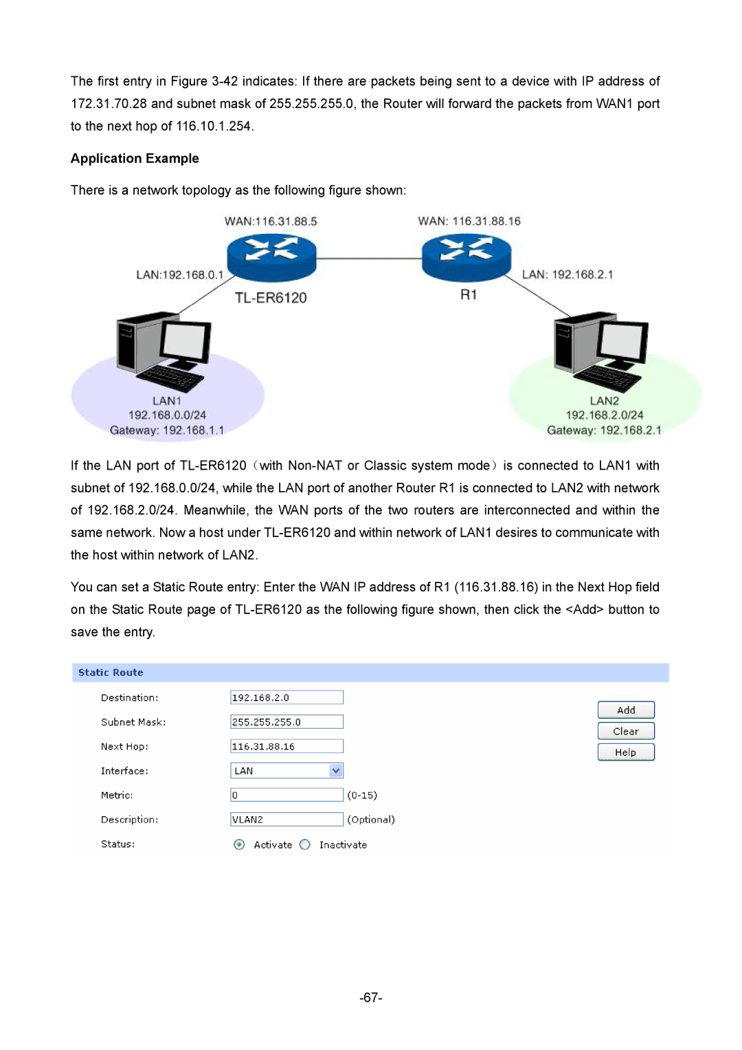
In addition to its security features, the TL-ER6120 offers support for VLAN configuration, allowing businesses to segment their networks for better performance and security. Dynamic Routing Protocols such as RIP v1/v2, and static routing are also supported, ensuring seamless data exchange across different network segments.
Another significant aspect of the TL-ER6120 is its Quality of Service (QoS) functionality. This feature enables users to prioritize bandwidth for critical applications, ensuring that services like VoIP and video conferencing maintain optimal performance. By managing the flow of data, businesses can enhance their operational efficiency.
The TL-ER6120 is equipped with several advanced management features, including a web-based user interface that simplifies network configuration and monitoring. Users can easily manage their network settings, view traffic statistics, and troubleshoot issues without advanced technical knowledge.
In conclusion, the TP-Link TL-ER6120 is an excellent choice for businesses seeking a reliable, feature-rich router. Its combination of security, performance, and ease of use makes it an ideal solution for managing business networks efficiently. Whether for load balancing, secure remote access, or network segmentation, the TL-ER6120 meets diverse business needs with sophistication and reliability.

