TL-SG3424P JetStream L2 Managed PoE Switch
REV2.0.0 1910010781
Copyright & Trademarks FCC Statement
Safety Information
Contents
Gvrp
VII
Viii
177
220
Package Contents
About this Guide
Intended Readers
Conventions
Overview of This Guide
System Switching Vlan Spanning Tree Multicast
QoS PoE ACL Network Security Snmp
Return to Contents
Overview of the Switch
Main Features
Introduction
Appearance Description
Front Panel
¾ LEDs
LED
Status Indication
Rear Panel
Login to the Switch
Login
Configuration
Return to Contents
System
System Info
System Summary
¾ Port Status
Port
Type
Speed
Status
Device Description
System Time
¾ Device Description
Daylight Saving Time
¾ DST Config
Predefined Mode
Recurring Mode
Date Mode
¾ IP Config
System IP
User Config
User Management
User Table
User ID, Name, Access Level and status Operation
¾ User Info
User Status
¾ User Table
Config Restore
Config Backup
¾ Config Restore
System Tools
Firmware Upgrade
¾ Config Backup
Access Security
System Reboot
System Reset
Access Control
¾ Access Control Config
¾ Session Config
IP Address&Mask
MAC Address
SSL Config
¾ Access User Number
SSH Config
¾ Global Config
¾ Certificate Download
¾ Key Download
Idle Timeout
Protocol
Max Connect
¾ Configuration Procedure
Key Type
Download
¾ Network Requirements
Application Example 2 for SSH
Page
Return to Contents
Switching
Port Config
Port
Port Select
Port Mirror
Description
Speed and Duplex
Flow Control
Group
Mirroring
Mode
Mirrored Port
Port Security
¾ Mirrored Port
Ingress
Egress
¾ Port Security
Max Learned MAC
Learned Num
¾ Port Isolation Config
Port Isolation
Loopback Detection
¾ Port Isolation List
Forward Portlist Display the forwardlist
Operation Mode
LAG
Interval It’s 3 seconds
LAG Table
LAG Table
Static LAG
¾ LAG Table
Group Number
Member
Lacp Config
Member Port
10 Lacp Config
¾ Lacp Config
Admin Key
Traffic Monitor
Traffic Summary
Port Priority
Packets Rx
Packets Tx
Octets Rx
Octets Tx
Traffic Statistics
Type Configuration Way Aging out
MAC Address
Bound
Address and the port
Address Table
Relationship
Static Address
¾ Search Option
¾ Address Table
Displays the corresponding Vlan ID of the MAC address
¾ Create Static Address
¾ Static Address Table
Dynamic Address
¾ Aging Config
¾ Dynamic Address Table
Filtering Address
Bind
¾ Create Filtering Address
¾ Filtering Address Table
Vlan
802.1Q Vlan
¾ Link Types of ports
¾ Pvid
Vlan Config
¾ Vlan Table
Vlan ID Select:
Select:
¾ Vlan Config
Enter the ID number of Vlan
Is valid or not
¾ Vlan Members
¾ Vlan Port Config
Port Displays the port number
Required. On the VLAN→802.1Q VLAN→Port Config page, set
¾ Vlan of Port
Vlan Description
Step Operation Description
Required. On the VLAN→802.1Q VLAN→VLAN Config
Optional. On the VLAN→802.1Q VLAN→VLAN Config
Protocol Vlan
¾ MAC Vlan Table
MAC Select
¾ Encapsulation Format of Ethernet Data
802.3 raw 802.2 LLC Snap Protocol
Protocol Group Table
Protocol Group
Vlan packets are processed in the following way
¾ Protocol Group Table
¾ Protocol Group Config
Protocol Template
¾ Protocol Group Member
Required. On the VLAN→802.1Q VLAN→Port Config
¾ Create Protocol Template
¾ Protocol Template Table
¾ Network Diagram
Application Example for 802.1Q Vlan
Required. On the VLAN→Protocol VLAN→Protocol
Optional. On the VLAN→Protocol VLAN→Protocol Vlan
Required. On VLAN→802.1Q VLAN→Port Config page, configure
Required. On VLAN→802.1Q VLAN→VLAN Config page, create a
Application Example for MAC Vlan
Operation Description
¾ Network Diagram ¾ Configuration Procedure
Application Example for Protocol Vlan
Required. On VLAN→Protocol VLAN→Protocol Template
Gvrp
On VLAN→Protocol VLAN→Protocol Group page, create protocol
¾ Gvrp
Registration Mode
Gvrp
Configuration Procedure
Spanning Tree
¾ STP Elements
¾ STP Timers
¾ Bpdu Comparing Principle in STP mode
¾ STP Generation
Step Operation
Tips :
¾ Rstp Elements
¾ Mstp Elements
¾ Port States
¾ Port Roles
STP Config
STP Config
Forward Delay
Version
Hello Time
Max Age
STP Summary
Port Config
STP Summary
Priority
ExtPath
IntPath
Edge Port
Region Config
Mstp Instance
Port Status
Instance Config
¾ Region Config
Instance Port Config
¾ Instance Table
Instance
Clear
Instance ID
Path Cost
Port Role
STP Security
Port Protect
¾ TC Protect
¾ Bpdu Protect
¾ Bpdu Filter
Loop Protect
Root Protect
TC Protect
Bpdu Protect
Application Example for STP Function
TC Protect
On Spanning Tree→STP Config→STP Config
On Spanning Tree→STP Config→Port Config
On Spanning Tree→MSTP Instance→Instance
Configure Switch D
¾ Suggestion for Configuration
Multicast
¾ Multicast Overview
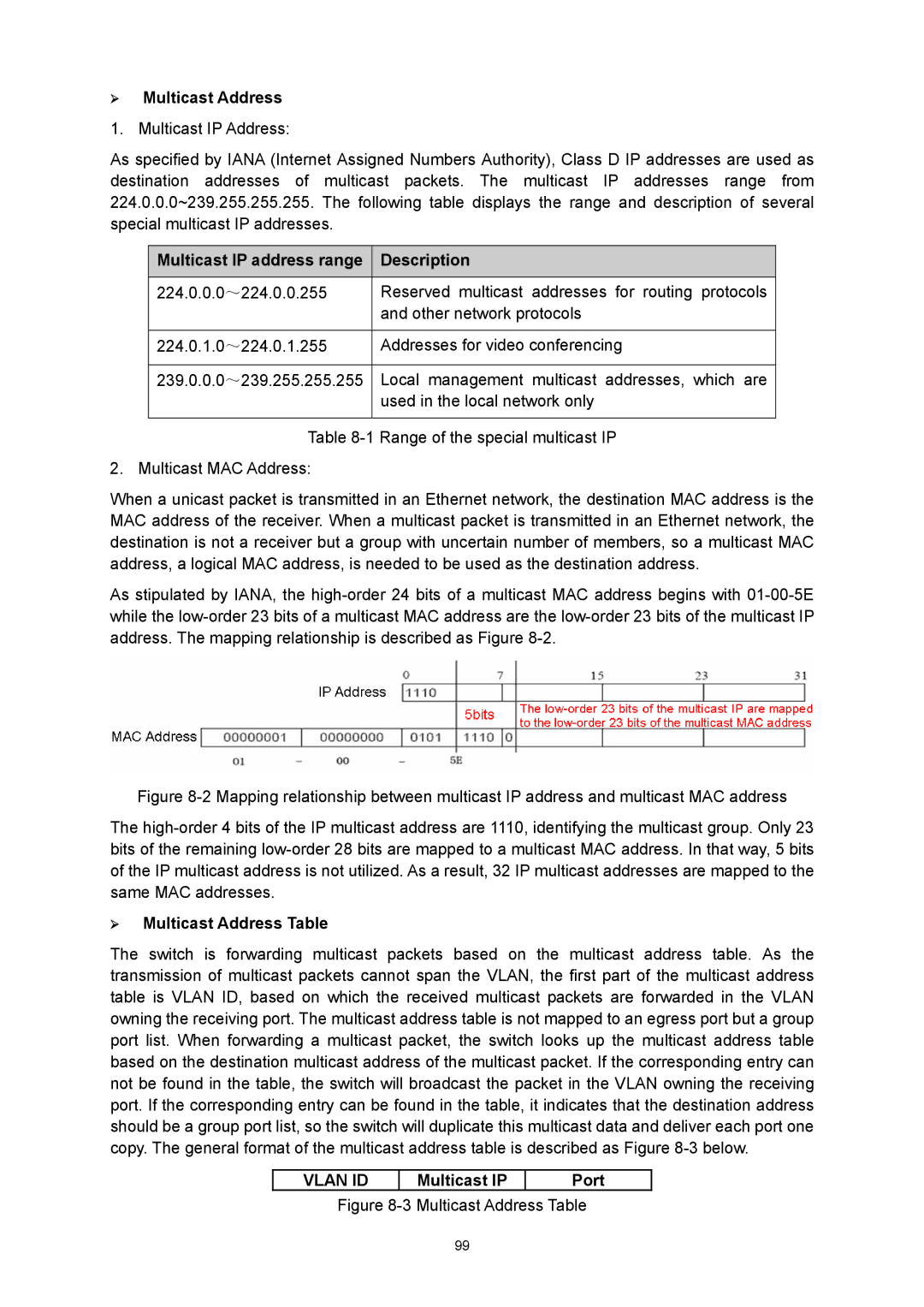
¾ Multicast Address
¾ Multicast Address Table
Multicast IP Port
Igmp Snooping
¾ Igmp Snooping
¾ Igmp Snooping Process
¾ Igmp Messages
Snooping Config
¾ Igmp Snooping Fundamentals
¾ Igmp Snooping Status
Description Displays Igmp Snooping status Member
Igmp Snooping
Fast Leave
Router Port Time
Member Port Time
Leave Time
Static Router Port
Snooping→Snooping Config and Port Config
Multicast→IGMP Snooping→VLAN Config
Multicast Vlan
Multicast→IGMP
¾ Multicast Vlan
Vlan
On the Multicast→IGMP Snooping→Snooping Config
Multicast→IGMP Snooping→Multicast Vlan
Snooping→Port Config
Snooping→Snooping Config
Multicast IP
Multicast IP Table
Static Multicast IP
Multicast Filter
IP-Range
¾ Create Static Multicast
¾ Static Multicast IP Table
Port Filter
IP Range ID
Start Multicast IP
End Multicast IP
¾ Port Filter Config
Action Mode
Filter
Bound IP-Range ID
Packet Statistics
Multicast→Multicast Filter→IP-Range
Multicast→Multicast Filter→Port Filter
¾ Igmp Statistics
¾ Priority Mode
QoS
¾ QoS
¾ Schedule Mode
117
¾ Port Priority Config
DiffServ
Port Priority
Displays the LAG number which the port belongs to
Required. On QoS→DiffServ→Schedule Mode
¾ Dscp Priority Config
Dscp Priority
Required. On QoS→DiffServ→Port Priority
3 802.1P/CoS mapping
¾ Priority Level
Required. On QoS→DiffServ→DSCP Priority
Schedule Mode
¾ Priority and CoS-mapping Config
¾ Schedule Mode Config
Bandwidth Control
Rate Limit
¾ Rate Limit Config
Storm Control
Ingress Rate Kbps
Egress RateKbps
¾ Storm Control Config
Port Broadcast Rate bps
Multicast Rate
Bps
¾ Port Voice Vlan Mode
Voice Vlan
Number OUI Address Vendor
¾ Security Mode of Voice Vlan
Security Packet Type Processing Mode
Global Config
12 Global Configuration
Port Mode
13 Port Config
OUI Config
Required. On VLAN→802.1Q VLAN→Port Config page, click
Mask
PoE Config
PoE
¾ Composition
¾ Advantage
PoE Config
PoE Status
PoE Priority
PoE Profile
PoE Time-Range
Time-Range Summary
¾ PoE Profile
Profile Name
PoE Time-Range Create
PoE Holiday Config
Index
End Time
Delete
ACL
Time-Range
¾ Time-Range Table
Time-Range Create
Holiday
Index Displays the index of the time-slice Start Time
ACL Config
Holiday Config
ACL Summary
ACL Create
¾ Rule Table
¾ Create ACL
MAC ACL
Rule ID
EtherType
User Priority
Standard-IP ACL
Extend-IP ACL
¾ Create Standard-IP ACL
¾ Create Extend-IP ACL
IP Protocol
TCP Flag :
IP ToS
Policy Config
Policy Summary
Policy Create
Action Create
¾ Create Policy
¾ Create Action
Policy Binding
Binding Table
¾ Policy Bind Table
¾ Port-Bind Config
Port Binding
Vlan Binding
Direction Displays the binding direction
¾ VLAN-Bind Config
Application Example for ACL
Enter the ID of the Vlan you want to bind
¾ VLAN-Bind Table
On ACL→ACL Config→ACL Create page, create ACL
On ACL→ACL Config→Standard-IP ACL page, select ACL
Network Security
IP-MAC Binding
Manual Binding
¾ Manual Binding Option
Enter the Vlan ID
Protect Type Select the Protect Type for the entry
¾ Manual Binding Table
ARP Scanning
Dhcp Snooping
Start IP Address
End IP Address
Scan
Network diagram for DHCP-snooping implementation
¾ Dhcp Working Principle
¾ Option
Dhcp Cheating Attack Implementation Procedure
¾ Dhcp Cheating Attack
¾ Dhcp Snooping Config
¾ Option 82 Config
¾ Port Config Port Select
Customization Circuit ID Remote ID
ARP Inspection
¾ Imitating Gateway
¾ Cheating Gateway
10 ARP Attack Cheating Gateway
¾ Cheating Terminal Hosts
¾ Man-In-The-Middle Attack
¾ ARP Flooding Attack
ARP Detect
¾ ARP Detect
¾ Trusted Port
ARP Defend
Required. On the Network Security→IP-MAC
Network Security→ARP
¾ ARP Defend
Defend
Current Speed
DoS Defend
ARP Statistics
¾ Illegal ARP Packet
DoS Attack Type Description
¾ Configure
¾ Architecture of 802.1X Authentication
12.4
¾ Defend Table
¾ The Mechanism of an 802.1X Authentication System
¾ 802.1X Authentication Procedure
19 PAP Authentication Procedure
¾ 802.1X Timer
¾ Guest Vlan
Authentication Method
802.1X
Guest Vlan
Guest Vlan ID
Supplicant Timeout
Server Timeout
Retry Times
Control Mode
¾ Authentication Config
Radius Server
Control Type
On the Network Security→802.1X→Global Config
Required. On the Network Security→802.1X→Radius
Required. On the Network Security→802.1X→Port
Snmp
¾ Snmp Overview
¾ Snmp Management Frame
¾ Snmp Versions
¾ Snmp Configuration Outline
¾ MIB Introduction
Snmp Config
¾ Local Engine
¾ Remote Engine
Snmp View
View Name
MIB Object ID
View Type
¾ Group Config
Snmp Group
Snmp User
Auth Mode
Auth Password
Privacy Mode
Privacy Password
¾ Community Config
Access
Snmp Community
Required. On the SNMP→SNMP Config→Global
Required. On the SNMP→SNMP Config→SNMP
MIB View
¾ Community Table
On the SNMP→SNMP Config→SNMP
Notification
Timeout
UDP Port
User
Retry
Rmon
¾ Notification Table
¾ Rmon Group
Rmon Group Function
Event Config
History Control
¾ History Control Table
Alarm Config
¾ Event Table
Alarm Type
Variable
Sample Type
Rising Threshold
194
Lldp
¾ Lldpdu Format
¾ TLV
TLV type TLV Name Description Usage
Basic Management TLV
Organizationally Specific TLV
Configuration/Status TLV
Power Via MDI TLV
Port Description TLV
System Capabilities TLV
Basic Config
Lldp
¾ Lldp Port Config
Lldp Port Config
Device Info
Local Info
Details
Neighbor Info
¾ Local Info
¾ Neighbor Info
Device Statistics
¾ Global Statistics
Errors
Transmit Total
Receive Total
Discards
Extended Power-Via-MDI TLV
¾ LLDP-MED Parameters Config
Location Identification TLV
Inventory TLV
¾ LLDP-MED Port Config
LLDP-MED Port Configuration
¾ Included TLVs
¾ Location Identification Parameters
Emergency
Civic Address
LLDP-MED Local Information
LLDP-MED Neighbor Information
Cluster
¾ Cluster Role
15.1 NDP
¾ Introduction to Cluster
NDP Summary
¾ Neighbor
Error NDP Packets
Aging Time
Send NDP Packets
Receive NDP Packets
NDP Config
Detail :
Enable
Disable
Ntdp
Device Table
Ntdp Summary
Port Displays the port number of the switch
Ntdp Summary
Ntdp Config
Ntdp Hop Delay
Ntdp Interval Time
Ntdp Hops
Cluster
Cluster Summary
¾ Global
Cluster
Cluster Config
¾ Global Config Cluster
¾ Current Role
¾ Role Change
14 Cluster Configuration for Individual Switch
Application Example for Cluster Function
On Cluster→NDP→NDP Config page, enable NDP
On Cluster→NTDP→NTDP Config page, enable
On Cluster→Cluster→Member Config page, select
On Cluster→Cluster→Cluster Topology
Maintenance
System Monitor
CPU Monitor
Memory Monitor
16.2 Log
Log Table
¾ Log Info
Time
Module
¾ Local Log Config
Local Log
Remote Log
Log Buffer
Backup Log
¾ Log Host
Host IP
Device Diagnostics
Error
Cable Test
Pair
Network Diagnostics
Loopback
Ping
¾ Ping Config
Tracert
¾ Tracert Config
Appendix a Specifications
Appendix B Configuring the PCs
Figure B-2
Now
Appendix C Load Software Using FTP
Hardware Installation
Configure the Hyper Terminal
239
Download Firmware via bootUtil menu
Figure C-5 Port Settings
TP-LINK upgrade You can only use the port 1 to upgrade
Are you want to upgrade the firmwareY/N y
TP-LINK start Start
User
Installation Guide
Appendix D 802.1X Client Software
244
245
Uninstall Software
Figure D-7 InstallShield Wizard Complete
Configuration
Figure D-11 Uninstall Complete
248
Figure D-16 Connection Status
FAQ
Appendix E Glossary
Multicast Switching
Generic Multicast Registration Protocol Gmrp
Group Attribute Registration Protocol Garp
Ieee 802.1D
Port Authentication
Remote Authentication Dial-in User Service Radius
Layer
Link Aggregation
Secure Shell SSH
Simple Network Management Protocol Snmp
Simple Network Time Protocol Sntp
Spanning Tree Algorithm STA