Model

Nomenclature

RTH

D

U

D

2

F

0

A0

U

A

G

3

A

4

L

A

L

G

3

F

2

L

A

L

1,2,3

4

5

6

7

8

9

10,11

12

13

14

15

16

17

18

19

20

21

22

23

24

25

26

27

Digits 01, 02, 03 – Series R


Digit 09 – Specials


Digit 18 – Evaporator Water Connection


RTH = Series R


X = No specials


L = Left Hand Evaporator Connection


Digit 04 – Dev Sequence


C = All specials denoted by digits elsewhere

R = Right Hand Evaporator Connection


S = Uncategorized special not denoted by

Digit 19 – Evaporator Connection Type


D = 4th Major Development


other

digits


Digit 05 – Design Control


Digits 10, 11 – Design Sequence


A = Standard Grooved Pipe


Digit 20 – Evaporator Waterside Pressure


U = WCBU


** = First Design, etc. increment when parts


are affected for service purposes


L = 150 psi


Digit 06 – Compressor Frame


H = 300 psi


B = B Compressor


Digit 12 – Agency Listing


C = C Compressor


X = No agency listing


Digit 21 – Condenser


D = D Compressor


U = C/UL


B = B Frame


E = E Compressor


D = D Frame


Digit 13 – Pressure Vessel Code


E = E Frame


Digit 07 – Compressor Capacity


A = ASME


F = F Frame


1 = Smaller Capacity for Frame


L = Chinese Pressure Vessel Code


G = G Frame


2 = Larger Capacity for Frame


3 = 50Hz Capacity


Digit 14 – Evaporator Frame


Digit 22 – Condenser Capacity


B = B Frame


1 = Tube count #1


Digit 08 – Unit Power Supply


C = C Frame


2 = Tube count #2


A = 200V/60Hz/3Ph power


D = D Frame


3 = Tube count #3


C = 230V/60Hz/3Ph power


E = E Frame


4 = Tube count #4


D = 380V/60Hz/3Ph power


F = F Frame


5 = Tube count #5


R = 380V/50Hz/3Ph power


G = G Frame


T = 400V/50Hz/3Ph power


Digit 23 – Condenser Tube Type


U = 415V/50Hz/3Ph power


Digit 15 – Evaporator Capacity


A = Enhanced Fin Copper


F = 460V/60Hz/3Ph power


1

= Tube count #1


B = Smooth Bore Copper


H = 575V/60Hz/3Ph power


2

= Tube count #2


C = Smooth Bore 90/10 CU/NI


3

= Tube count #3


4

= Tube count #4


Digit 24 – Condenser Passes


5

= Tube count #5


2 = 2 Pass


6

= Tube count #6


Digit 25 – Condenser Water Connection


Digit 16 – Evaporator Tube Type


L = Left Hand Connection


A = Enhanced Fin Copper


R = Right Hand Connection


Digit 17 – Evaporator Water Pass


Digit 26 – Condenser Connection Type


Configuration


A = Standard Grooved Pipe


2

= 2 pass


C = Marine


3

= 3 pass


Digit 27 – Condenser Waterside Pressure


4

= 4 pass


L = 150 psi


H = 300 psi


14

RLC-PRC020-EN

Page 14
Image 14
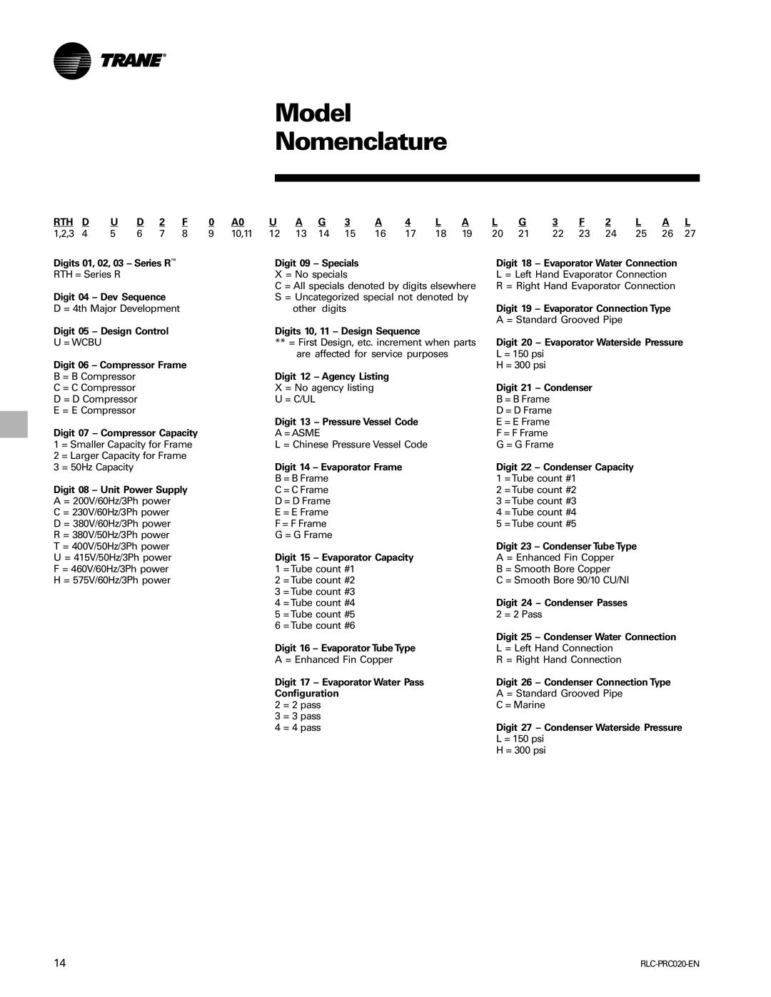
Trane RTHD manual Model Nomenclature, Rth

RTHD specifications

The Trane RTHD is a highly efficient and innovative HVAC solution designed for commercial and industrial applications. With a focus on reliability, performance, and energy efficiency, the RTHD series offers a wide range of features that set it apart from conventional heating and cooling systems.

One of the standout characteristics of the Trane RTHD is its robust construction. Built to withstand the rigors of daily use in demanding environments, the unit boasts a durable and weather-resistant cabinet. This design not only ensures longevity but also helps protect internal components from external elements.

Energy efficiency is at the forefront of the RTHD's design philosophy. The unit utilizes advanced technologies such as Variable Frequency Drive (VFD) for its compressor and fans. This allows for precise adjustment of the cooling and heating output, optimizing energy consumption based on real-time demand. As a result, the RTHD can achieve impressive Seasonal Energy Efficiency Ratios (SEER) and Heating Seasonal Performance Factors (HSPF), making it an environmentally friendly choice.

Another key feature of the RTHD is its compatibility with various control systems. The unit supports Trane's advanced control technology, enabling integration with building management systems for enhanced monitoring and operational efficiency. This capability allows facility managers to leverage data-driven insights to optimize performance and maintenance schedules.

The RTHD also incorporates innovative sound-reducing technologies, which ensure quiet operation, a significant consideration for settings where noise reduction is essential. Features such as acoustic insulation and strategically designed fan blades help minimize sound levels, making the RTHD suitable for a variety of commercial environments.

Ease of maintenance is another important aspect of the Trane RTHD. The design includes accessible components for quick servicing, minimizing downtime and overall maintenance costs. Additionally, Trane provides comprehensive support and resources to ensure that technicians can efficiently maintain and troubleshoot the system.

In summary, the Trane RTHD is a leading-edge HVAC solution that combines durability, energy efficiency, advanced control options, and quiet operation. With its range of features and technologies, it is well-equipped to meet the demands of modern commercial and industrial spaces, solidifying its reputation as a trusted choice in the HVAC market. Whether for new installations or upgrades, the RTHD delivers reliability and performance that customers can depend on for years to come.